Chamfer hob and method of use thereof

Inactive Publication Date: 2005-09-06
ARVIN JOSEPH L
View PDF16 Cites 25 Cited by
  • Summary
  • Abstract
  • Description
  • Claims
  • Application Information

AI Technical Summary

Problems solved by technology

Gear teeth are provided as a result of the hobbing operation in an unfinished state, and may result in the teeth having a burr and sharp edges following the initial hobbing operation.
It is generally undesirable to have sharp corners on gear teeth because as gear teeth mesh during gear operation, there is a tendency to stress the contact points of the gear teeth, leading to chipping or other deformation, which events may detract from continued smooth operation of the gears.
The stresses on the gears as they mesh during operation are magnified and any slight imperfection or defect in the configuration of the gear teeth may cause undesirable chipping or bending stress cracks, ultimately resulting in catastrophic failure of the gears.
One of the problems that contributes to gear teeth deformities is the asymmetrical configuration of the chamfered end of a standard gear made in accordance with the equipment and method of conventional gears, for example, of aforementioned U.S. Pat. No. 2,451,447.
The lack of a chamfered or beveled edge surface on both ends of the gear

Method used


Image

  • Chamfer hob and method of use thereof
  • Chamfer hob and method of use thereof
  • Chamfer hob and method of use thereof

Examples


Embodiment Construction

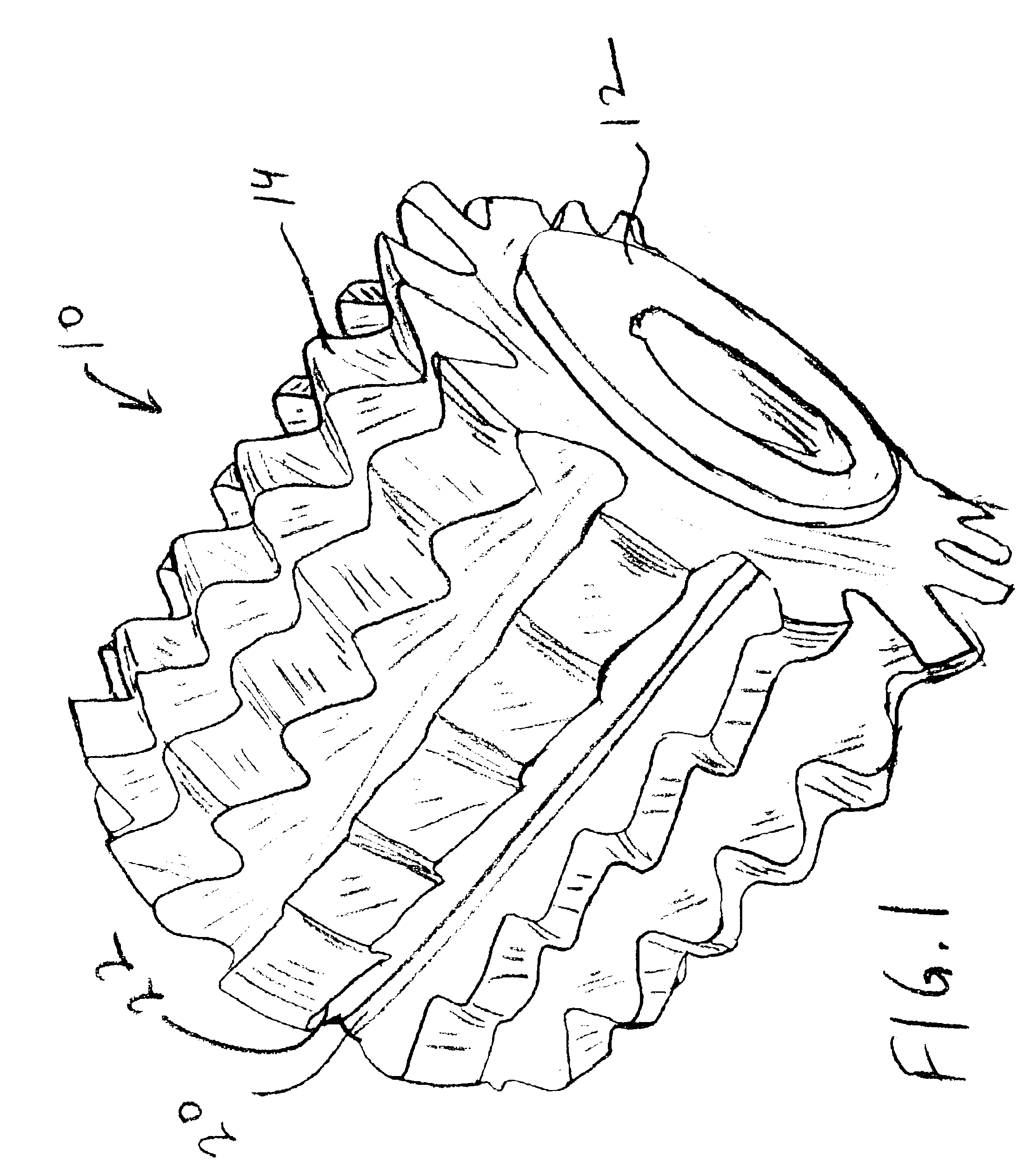
[0025]FIG. 1 shows in a perspective view, a hob 10 for providing a chamfer to both ends of a gear blank, which has previously been rough cut, is used at a stage after the gear teeth have been cut by a first hobbing procedure. A central bore 12 permits the insertion of the hob 10 over a shaft (not shown in FIG. 1) for facilitating gear blank rotation. The hob 10 is generally cylindrical in shape, and will have a number of cutting or milling teeth 14, arranged in longitudinal rows, as shown. Each tooth 14 essentially takes on the shape of sine wave, so that a row 16 of teeth 14 viewed in cross-section will appear as a virtually sinusoidal pattern. The exact shape of each tooth is a significant feature of the invention, as will be described below.

[0026]Although the teeth may initially be seen as being in identical and radially symmetrical rows, closer inspection will show, as is known by those with ordinary skill in the art, that each row of teeth is slightly offset in the axial or lon...


PUM

PropertyMeasurementUnit
Angleaaaaaaaaaa
Angleaaaaaaaaaa
Thicknessaaaaaaaaaa

Abstract

A chamfer hob for and a method of providing a chamfered end and having an identical chamfer angle at both a front face and a back face of a gear including a shaft, a plurality of helical cutting vanes extending radially outwardly from the shaft, such that the radially outward surface of the cutting vanes defines a hob diameter, and a hob radius, a predetermined radial width of the desired chamfer and a depth of chamfer, such that the chamfering is done on both faces of the gear teeth ends resulting in a uniform chamfer around the periphery of the complete gear tooth. The method includes the steps of providing a blank gear die, including a gear shaft and a disk having a front face distally disposed from the gear shaft and back face proximally disposed to the gear shaft, each of the front and back faces having gear, providing a gear hob and a chamfer hob on a single hob spindle, the chamfer hob having a plurality of helical cutting vanes extending radially outwardly from the hob shaft, such that the radially outwardly extending surface of the cutting vanes, mounting the gear blank on a mount, mounting the hob spindle, including the gear hob and the chamfer hob, on a mounting device for rotation therewith, bringing the gear hob in proximity to and in contact with the edges of the gear blank so as to form gear teeth on the gear blank, bringing the chamfer hob in proximity to and in contact with the edges along the front face of the gear teeth formed in the preceding step so as to produce a uniform chamfer around the edges of the gear teeth and bringing the gear hob in proximity to and in contact with the edges along the back face of the gear teeth formed so as to produce a uniform chamfer around the edges of the gear teeth.

Description

BACKGROUND OF THE INVENTION[0001]1. Field of the Invention[0002]This invention relates generally to hobbing machines, and more specifically, to hobbing machines in which finishing operations including gear teeth cutting, deburring and double sided chamfering are performed in several operational steps using a single automated hob spindle.[0003]2. Background Art[0004]Gear teeth are usually cut or milled in automated machines, sometimes referred to as hobbing machines. These machines operate on a usually cylindrical or disc-shaped gear blank by sequentially cutting or milling the gear teeth using a conventional commercially available hobbing machine. Examples of such hobbing machines are described in U.S. Pat. No. 2,451,447, No. 3,130,642 and No. 6,116,828.[0005]Gear teeth are provided as a result of the hobbing operation in an unfinished state, and may result in the teeth having a burr and sharp edges following the initial hobbing operation. Accordingly, a second finishing operation h...

Claims


Application Information

Patent Timeline
IPC IPC(8): B23F19/00B23F19/10B23F21/16B23F21/00
CPCB23F19/104B23F21/005B23F21/16Y10T407/1715Y10T409/101749Y10T409/10159
Inventor ARVIN, JOSEPH L.GRUBEL, HERBERT A.
Owner ARVIN JOSEPH L
Why Eureka
Try Eureka