Adjustable pedal system for exercise bike

a pedal system and exercise bike technology, applied in the field of adjustable pedal systems for exercise bikes, can solve the problems of overstressing the replacement knee, virtually impossible for the average patient to achieve a complete revolution of the pedals during the early phases of post-operation rehabilitation, and the total radius of the rotational movement of the pedals is simply too great for many patients

Inactive Publication Date: 2009-08-27
MULE LEONARD
View PDF2 Cites 52 Cited by
  • Summary
  • Abstract
  • Description
  • Claims
  • Application Information

AI Technical Summary

Benefits of technology

[0009]With the present pedal adjustment system, the pedals can be moved along the crank arm of a crank mechanism of an exercise bike to thereby adjust the throw or radius of rotational movement of the pedals about a main shaft of rotation.
[0011]Once intermeshed, the locking members lock the pedals in the desired positions and that locked position is maintained by the use of a clamping device such as a thumb screw or knob that holds the locking members in that intermeshed condition. The thumb screw itself can be readily manipulated by the user without the need for special tools.
[0014]Accordingly, there is a system of the present invention that is built into or located proximate to the exercise bike that provides a continuous measurement of the angle of the knee while the patient is carrying out normal exercises on the bike.

Problems solved by technology

A problem occurs, however, in that the normal throw or total radius of the rotational movement of the pedals is simply too great for many patients and it can overstress the replacement knee.
In the case of exercise bikes, the present fixed pedal location of many such bikes has a rotation diameter of about 13 inches (33 cm.) and which makes it virtually impossible for the average patient to achieve a complete revolution of the pedals during the early phases of post operation rehabilitation.
The ability to change the radius of the rotational movement of the pedals has been published, see U.S. Pat. No. 7,204,788 of Andrews and U.S. Pat. No. 5,338,272 of Sweeney, III however, in most cases, the mechanism or system is relatively complex, requires tools and / or specialized knowledge, and is limited in the ability to move the pedals along positive, multiple positions and the like.

Method used


Image

  • Adjustable pedal system for exercise bike
  • Adjustable pedal system for exercise bike
  • Adjustable pedal system for exercise bike

Examples


Embodiment Construction

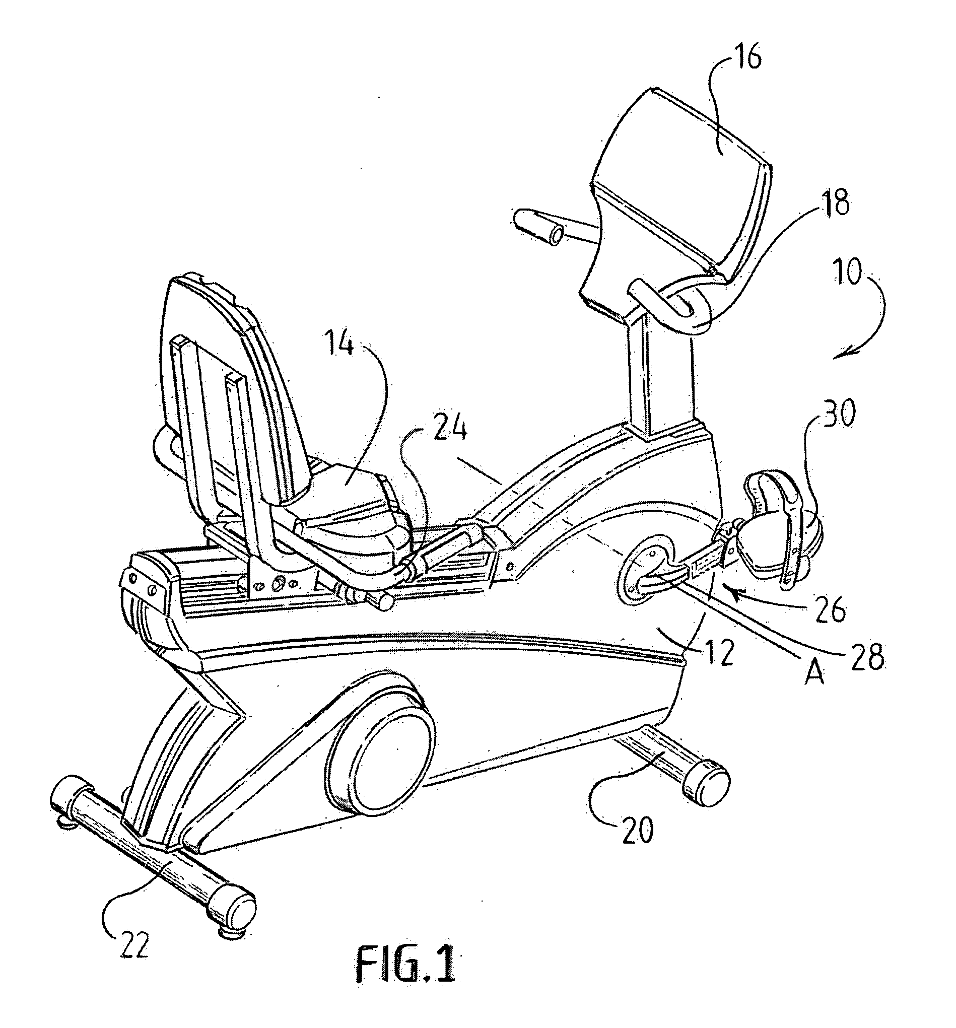
[0027]Referring now to FIG. 1, there is shown a perspective view of an exercise bike 10 having included, therewith the pedal adjustment system of the present invention. The illustration is that of a recumbent bike to which the present invention is particularly adapted. As can be seen, the exercise bike 10 comprises a frame 12 having various conventional components, such as a seat 14, a display panel 16 to view certain parameters of the exercise routine, handle bars 18 and base members 20, 22 to retain the exercise bike 10 in a stable upright orientation. As can be seen, the seat 14 is adjustable in accordance with the particular user and the seat adjustment can be accomplished in a conventional manner. A second set of handle bars 24 is present for use by a user when in a reclined position.

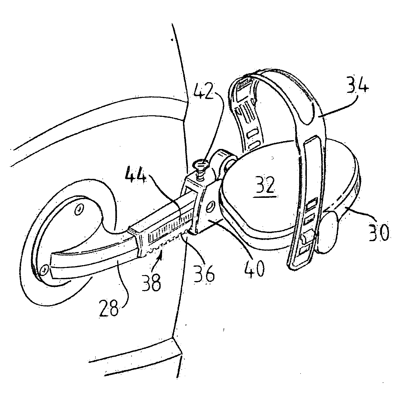
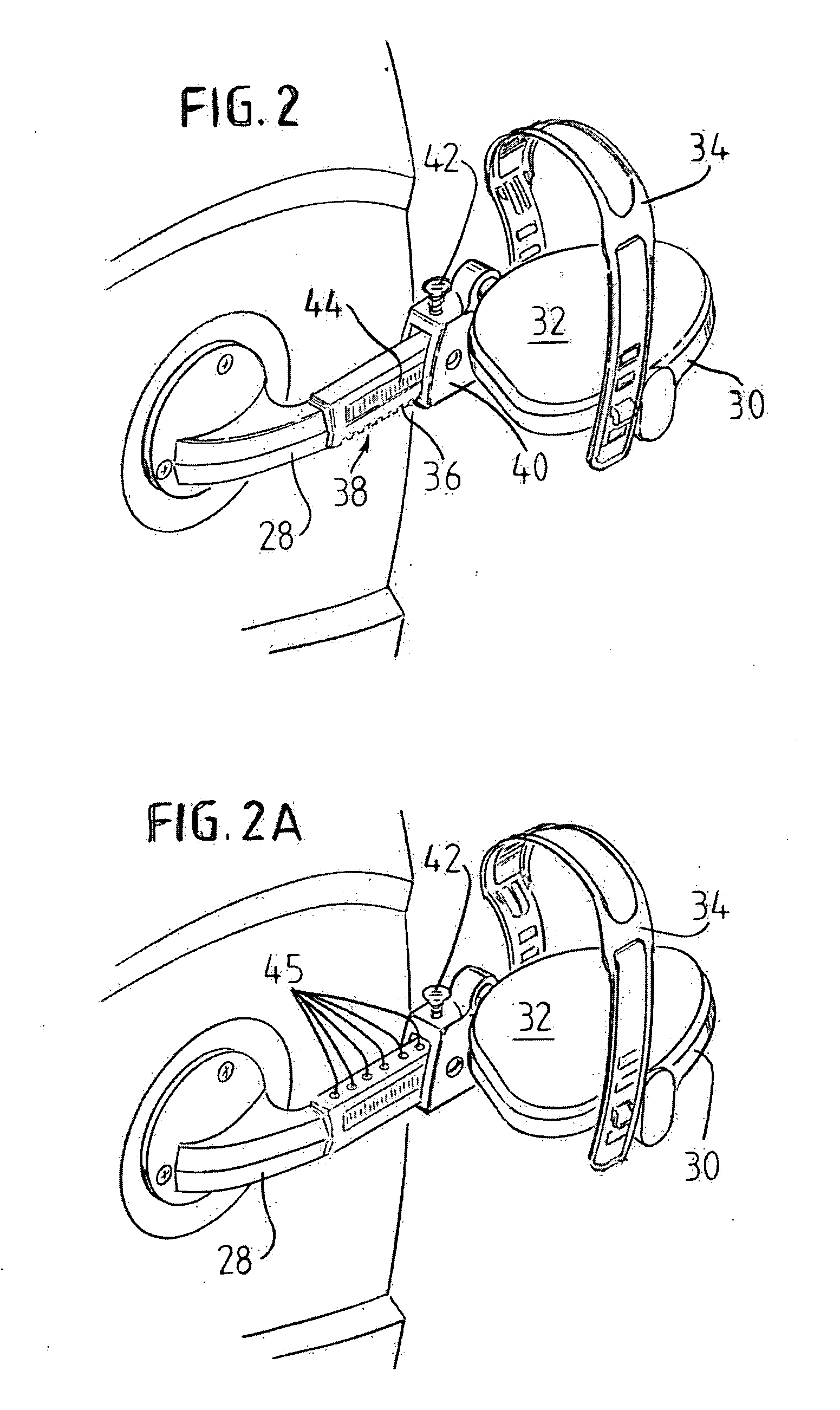
[0028]The exercise bike 10 also includes a crank mechanism 26 that includes a main shaft, not shown in FIG. 1, that passes through the frame along the horizontal axis A and a pair or crank arms. On...


PUM


Abstract

An adjustable pedal system for changing the position of pedals along the crank arms of an exercise bike. The system provides a locking member, such as a rack, located along the crank arm and a locking member, such as one or more gear teeth formed on a slide sleeve to which the pedal is affixed. Thus the slide sleeve and pedal can be slid along the crank arm to the desired position whereupon the locking members intermesh to positively lock the pedal in the desired location. The intermeshing is maintained by a clamping device, such as a thumb screw that is tightened to lock the pedals in the desired location and loosened to disengage the locking members to allow the movement of the pedals to another location. The system can be operated without the need for tools and can be retrofitted to existing exercise bikes.

Description

BACKGROUND [0001]The present invention relates to a system for adjusting the pedal location along a crank arm of an exercise bike, and, more particularly, to a simple, tool less system that allows a user to change the location of the pedals of an exercise bike along the crank arm to adjust the throw or radius of the rotational movement.[0002]There are a number of differing exercise bikes currently available commercially. While there are certainly differences in such exercise bikes, in general, most have some frame with a crank mechanism having a center shaft that passes through the frame along a generally horizontal axis and having two crank arms that extend outwardly in parallel planes and spaced at 180 degrees apart. There are also pedals that are affixed in one manner or another to the crank arms such that the user can place both feet into the pedals and rotate the crank mechanism in a rotational movement for exercise, therapy or both.[0003]In many of such exercise bikes, the thr...

Claims


Application Information

Patent Timeline
Patent Type & Authority Applications(United States)
IPC IPC(8): B62M3/02A63B22/06
CPCA63B2022/0623A63B2208/0238A63B2220/10A63B2220/833Y10T74/2172B62M3/02A63B22/0046A63B22/0605A63B2022/0652A63B2225/09
Inventor MUL'E, LEONARD
Owner MULE LEONARD
Why Eureka
Try Eureka