Connector for plural mating connectors having different shapes of interfaces

a technology of connectors and interfaces, applied in the field of connectors, can solve the problems of two types of connectors not being compatible with each other, affecting the connection between a high resolution display and an instrument producing low resolution signals, and affecting the quality of the signal

Inactive Publication Date: 2005-09-06
JAPAN AVIATION ELECTRONICS IND LTD
View PDF15 Cites 110 Cited by
  • Summary
  • Abstract
  • Description
  • Claims
  • Application Information

AI Technical Summary

Benefits of technology

[0017]In the connector according to this invention, the partition mechanism may be designed and arran...

Problems solved by technology

On the other hand, a connector for high resolution transmission can in theory be used in low resolution transmission, but there is a problem that the size of a connector for high resolution transmission is bigger than one of a connector f...

Method used


Image

  • Connector for plural mating connectors having different shapes of interfaces
  • Connector for plural mating connectors having different shapes of interfaces
  • Connector for plural mating connectors having different shapes of interfaces

Examples


first embodiment

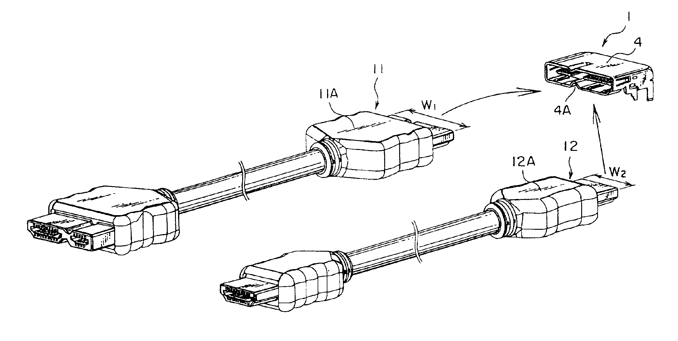
[0049]With reference to FIGS. 6 to 8, a receptacle connector 1 according to the present invention can accommodate therein either a plug connector 11 having a width W1 or a plug connector 12 having a width W2, both plug connectors 11 and 12 being covered by hoods 11A and 12A, respectively. Especially, the larger plug connector 11 has a connector interface or an interface hole which comprises two interface portions different in shape from each other, while the smaller plug connector 12 has a connector interface corresponding to one of the interface portions of the connector 11.

[0050]The connector 1 comprises an insulator 2, a plurality of contacts 3 supported by the insulator, and a shell 4 covering the insulator 2 and the contacts 3. The shell 4 defines a connector interface or interface hole on one end thereof in an insertion direction, namely an X-direction in FIG. 7.

[0051]Specifically, the shell 4 comprises two partitioning portions 4A which serve as partition means or mechanism. ...

second embodiment

[0061]In the above-mentioned structure or the modification thereof, the partition means or mechanism (2B, 6) completely and physically divides the connector interface into two interface portions. In the next embodiment, partition means or mechanism also divides the connector interface into a plurality of sections completely and physically. That is, the receptacle connector according to the next embodiment can handle the type of larger plug connector shown in FIG. 12.

[0062]With reference to FIG. 15, although the receptacle connector 1 according to a third embodiment of the present invention comprises an insulator 2, a plurality of contacts 3, and a shell 4, similar to the abovementioned first embodiment, the insulator 2 and contacts 3 are not shown in the figure for the purpose of simplification of the drawing. In addition, six contact portions 4B are also formed in the same manner of the first embodiment. The receptacle connector 1 can accommodate therein either a larger plug conne...

third embodiment

[0064]In the connector of the third embodiment, the partitioning wall portion 4G may further have protrusions 4H as shown in FIG. 16. In the manufacturing process, the protrusions 4H are inserted into holes 41 formed in the upper wall of the shell 4, and then are mauled or deformed by hammer or something, so that the partitioning wall portion 4G is fixed within the shell 4.

[0065]Also, the partitioning wall portion 4G may further have a tab or lug 4J in place of the protrusions, as shown in FIG. 17. In the manufacturing process, the tab 4J is inserted into a slit 4K formed in the upper wall of the shell 4, and then is bent, so that the partitioning wall portion 4G is fixed within the shell 4.

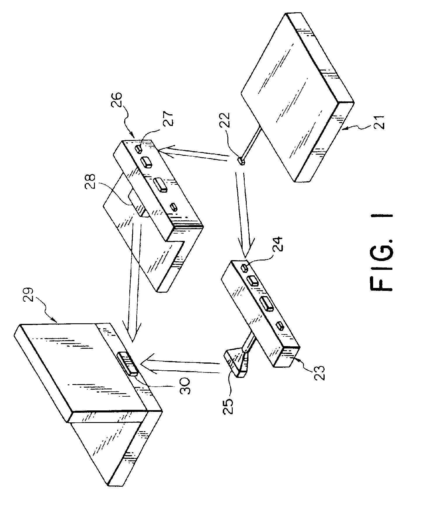
[0066]Consider here that the above-mentioned connectors are applied to the configuration illustrated in FIG. 1. In that case, all connection mentioned with reference to FIG. 1 can be established naturally. In addition, the connector 22 may be directly connected to the connector 30, provided the i...


PUM


Abstract

A partition mechanism is arranged in a shell of a receptacle connector so that a connector interface defined by the shell is partitioned into two interface portions, one of which has a shape different from the other. Therefore a mating connector for the connector can be connected with one or two interface portions, depending on a shape of a connector interface of the mating connector. In an example, a plug connector for high resolution signals is connected with two interface portions of the receptacle connector, while another plug connector for low resolution signals is connected with only one interface portion of the receptacle connector.

Description

BACKGROUND OF THE INVENTION[0001]This invention relates to a connector, in particular, to a connector for use in high-rate serial transmission for video stream.[0002]As typical ones of high-rate serial transmission techniques for video signals, TMDS, LVDS and GVIF are known. TMDS stands for Transition Minimized Differential Signaling, which is a standard as to a video data transmission between a general computer and its monitor or display. In TMDS standard, data transmission is carried out through two signal lines, negative and positive lines, and a ground line. LVDS stands for Low Voltage Differential Signaling, which is one of high-rate serial transmission systems and is mainly used as an input interface for a liquid crystal panel installed in a notebook computer. In LVDS system, data are transmitted in the form of low amplitude differential signals. GVIF stands for Gigabit Video Interface, which is one of high-rate serial transmission systems and is often used as an input interfa...

Claims


Application Information

Patent Timeline
IPC IPC(8): H01R27/00H01R27/02G06F1/18H01R12/71H01R13/648H01R24/00H01R24/58H01R31/06
CPCH01R27/02H01R31/06
Inventor KATO, NOBUKAZUIGARASHI, ISAOHAYASHI, KOJI
Owner JAPAN AVIATION ELECTRONICS IND LTD
Why Eureka
Try Eureka