Fixturing assembly

a technology of fixing assembly and heart valve, which is applied in the field of biological implantable prostheses and heart valve assembly, can solve the problems of increasing the chance of mistakes, time-consuming and cumbersome attachment of sewing rings to valve orifices, and increasing the complexity of suturing

Inactive Publication Date: 2005-09-06
MEDTRONIC INC
View PDF22 Cites 393 Cited by
  • Summary
  • Abstract
  • Description
  • Claims
  • Application Information

AI Technical Summary

Benefits of technology

[0022]An embodiment of a method of increasing and maintaining the size of a biological valve annulus includes placing a circumferentially expandable first prosthesis in the annulus. The method also includes circumferentially expanding the first prosthesis, and circumferentially locking the first prosthesis.
[0023]Circumferentially expanding the first prosthesis can include increasing the radius of the annulus from about 0.1 mm (0.004 in.) to more than about 2.0 mm (0.08 in.). The first prosthesis can also have an engagement element configured to receive a second prosthesis.

Problems solved by technology

Sewing rings can be tedious to secure to the valve orifice.
Further, attaching the sewing ring to the annulus can be time consuming and cumbersome.
The complexity of suturing provides a greater opportunity for mistakes and requires a patient to be on cardiopulmonary bypass for a lengthy period.
A patient can also have a natural valve lumen that is detrimentally small.

Method used


Image

  • Fixturing assembly
  • Fixturing assembly
  • Fixturing assembly

Examples


Embodiment Construction

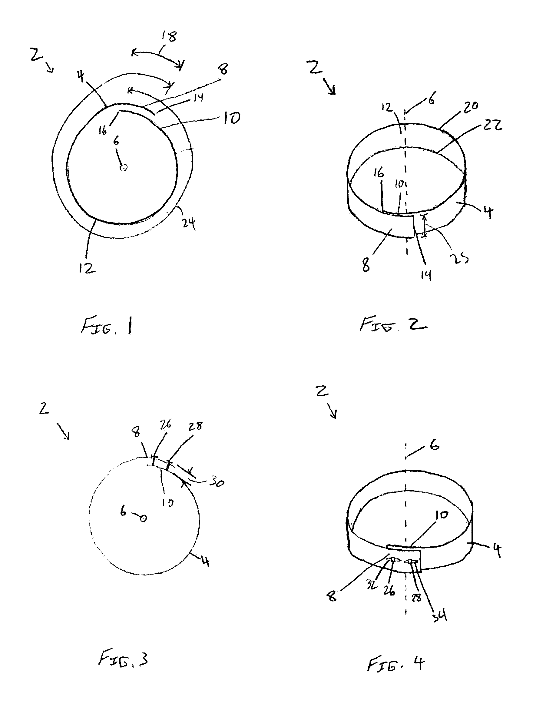
[0066]FIGS. 1 and 2 illustrate an embodiment of a biologically implantable first prosthesis 2. The first prosthesis 2 can have a wall 4. The wall 4 can have material strength and dimensions known to one having ordinary skill in the art to make the first prosthesis resiliently expandable. The wall 4 can have an open form or spiral longitudinal cross-section, as shown in FIG. 1. The longitudinal cross-section can be perpendicular to a central longitudinal axis 6.

[0067]The wall 4 can have a first terminal end 8 and a second terminal end 10. Each end 8 and 10 can be defined from a midpoint 12 of the wall 4 to a first terminus 14 or a second terminus 16 of the wall 4 at the respective end 8 or 10. The wall 4 can have an end difference length 18. The end difference length 18 can be the shortest angular length from the first terminus 14 to the second terminus 16. The wall 4 can also have a leading edge 20 and a trailing edge 22. The leading edge 20 and trailing edge 22 can be substantially...


PUM


Abstract

A fixturing assembly is provided that includes a needle and a fixturing device. The needle includes a first sharpened end and a second end including a can. The fixturing device includes an elongate filament having first and second ends, and an enlarged fixturing device on the first end of the filament. The second end of the filament is held by the can by frictional resistance, the second end of the filament being removable from the can when a tensile force is applied between the needle and the second end of the filament that exceeds the frictional resistance. For example, the can may include a coil, corrugations, or a roughened inner surface to removably hold the end of the fixturing device.

Description

CROSS-REFERENCE TO RELATED APPLICATIONS[0001]This is a continuation of application Ser. No. 10 / 327,821, filed Dec. 20, 2002.BACKGROUND OF THE INVENTION[0002]1. Field of the Invention[0003]The present invention relates generally to a biologically implantable prosthesis, a heart valve assembly using the prosthesis, and methods of using the same within an annulus of the body.[0004]2. Description of the Related Art[0005]Prosthetic heart valves can replace defective human valves in patients. Prosthetic valves commonly include sewing rings or suture cuffs that are attached to and extend around the outer circumference of the prosthetic valve orifice.[0006]In a typical prosthetic valve implantation procedure, the heart is incised and the defective valve is removed leaving a surrounding area of locally tougher tissue. Known heart valve replacement techniques include individually passing sutures through the tough tissue to form an array of sutures. Free ends of the sutures are extended out of...

Claims


Application Information

Patent Timeline
Patent Type & Authority Patents(United States)
IPC IPC(8): A61F2/24A61B17/00A61B17/04A61B17/06A61F2/02
CPCA61B17/0401A61F2/2409A61F2/2412A61F2/2445A61B2017/00243A61B2017/0406A61B2017/0417A61B2017/0496A61B2017/0608A61F2/2415A61F2002/30545A61F2250/001Y10S623/91A61F2220/0016A61F2220/0041A61F2220/0066A61F2220/0075
Inventor FOGARTY, THOMAS J.DREWS, MICHAEL J.HOLMGREN, NEILMODESITT, D. BRUCE
Owner MEDTRONIC INC
Why Eureka
Try Eureka