Etching method in fabrications of microstructures

a technology of microstructures and etching methods, which is applied in the direction of semiconductor/solid-state device testing/measurement, separation processes, instruments, etc., can solve the problems of inefficient use of etching, difficult control of etching process, and unfavorable etching process

Inactive Publication Date: 2005-09-06
VENTURE LENDING & LEASING IV +1
View PDF10 Cites 10 Cited by
  • Summary
  • Abstract
  • Description
  • Claims
  • Application Information

AI Technical Summary

Problems solved by technology

This etch process is unfavorable because the continuous flowing of the gas etchant etches the sacrificial layers too fast which makes the etching process difficult to control.
Moreover, the continuous flow is inefficient in usage of etchant.
However, it also has disadvantages.
In addition, because the amount of the etchant fed into the etching system at one time is fixed and the maximum amount of the sacrificial material that can be removed by the fixed amount of the etchant is limited for a given etching system, the maximum amount of the etchant fed into the etching at one time may not be enough to remove a larger amount of the sacrificial material.
This feeding process, however, may cause “etch front marks” and / or etching un-uniformities in the microstructures after etch.

Method used


Image

  • Etching method in fabrications of microstructures
  • Etching method in fabrications of microstructures
  • Etching method in fabrications of microstructures

Examples


Embodiment Construction

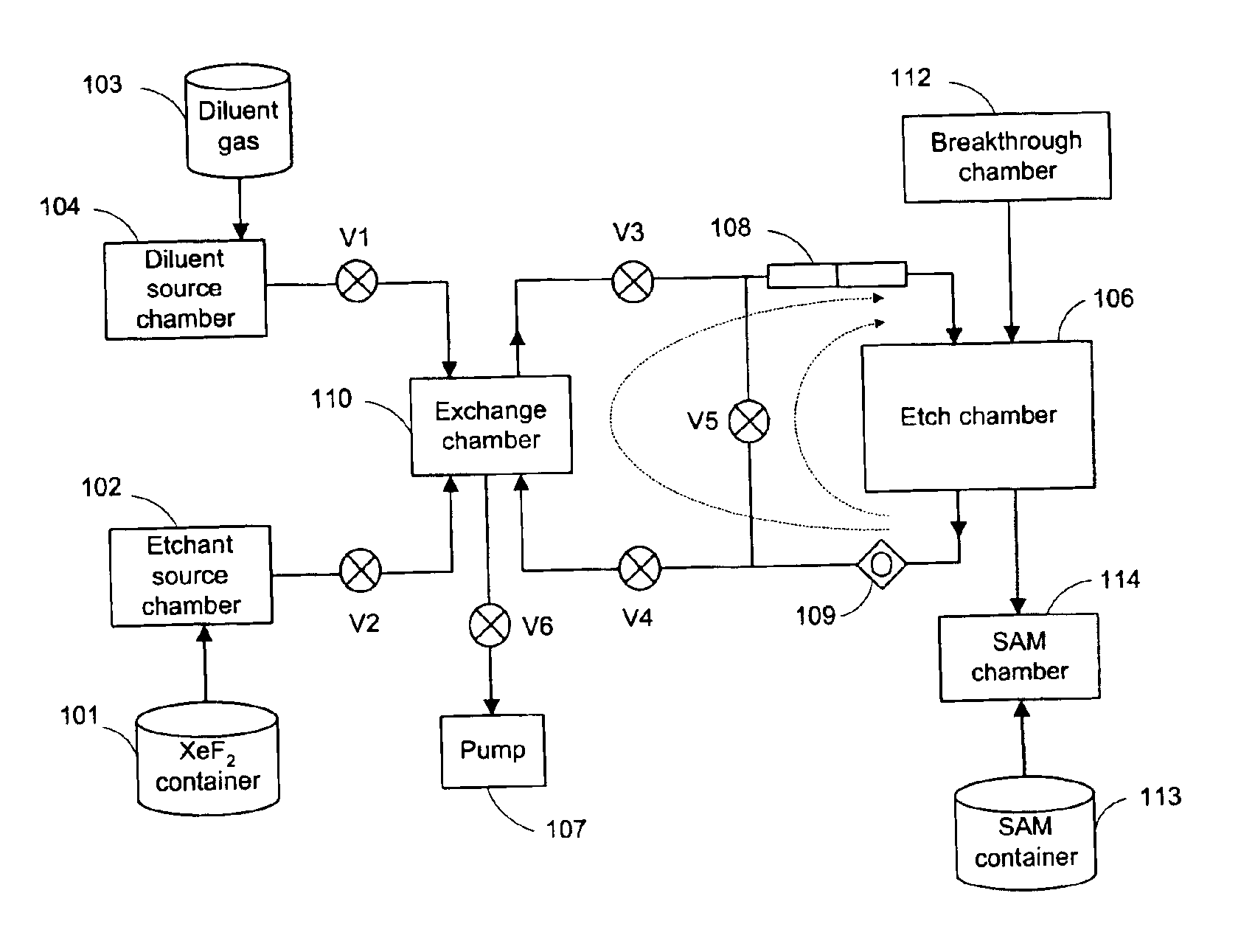
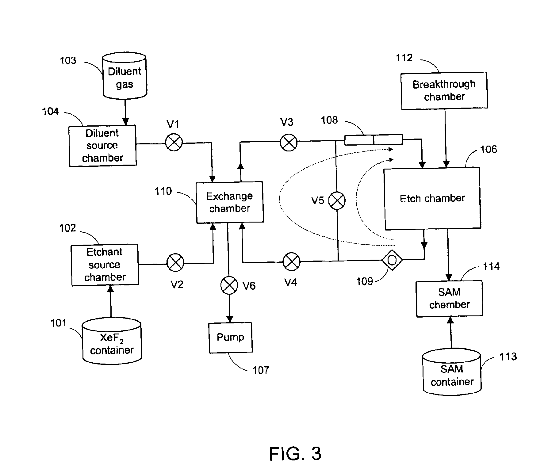
[0017]The present invention teaches a method for removing sacrificial materials in fabrications of microstructures using one or more selected spontaneous vapor phase etchants. The etchant is fed into the etch chamber during a feeding cycle of a sequence of feeding cycles until the sacrificial material of the microstructure is consumed by the chemical reaction between the etchant and the sacrificial material.

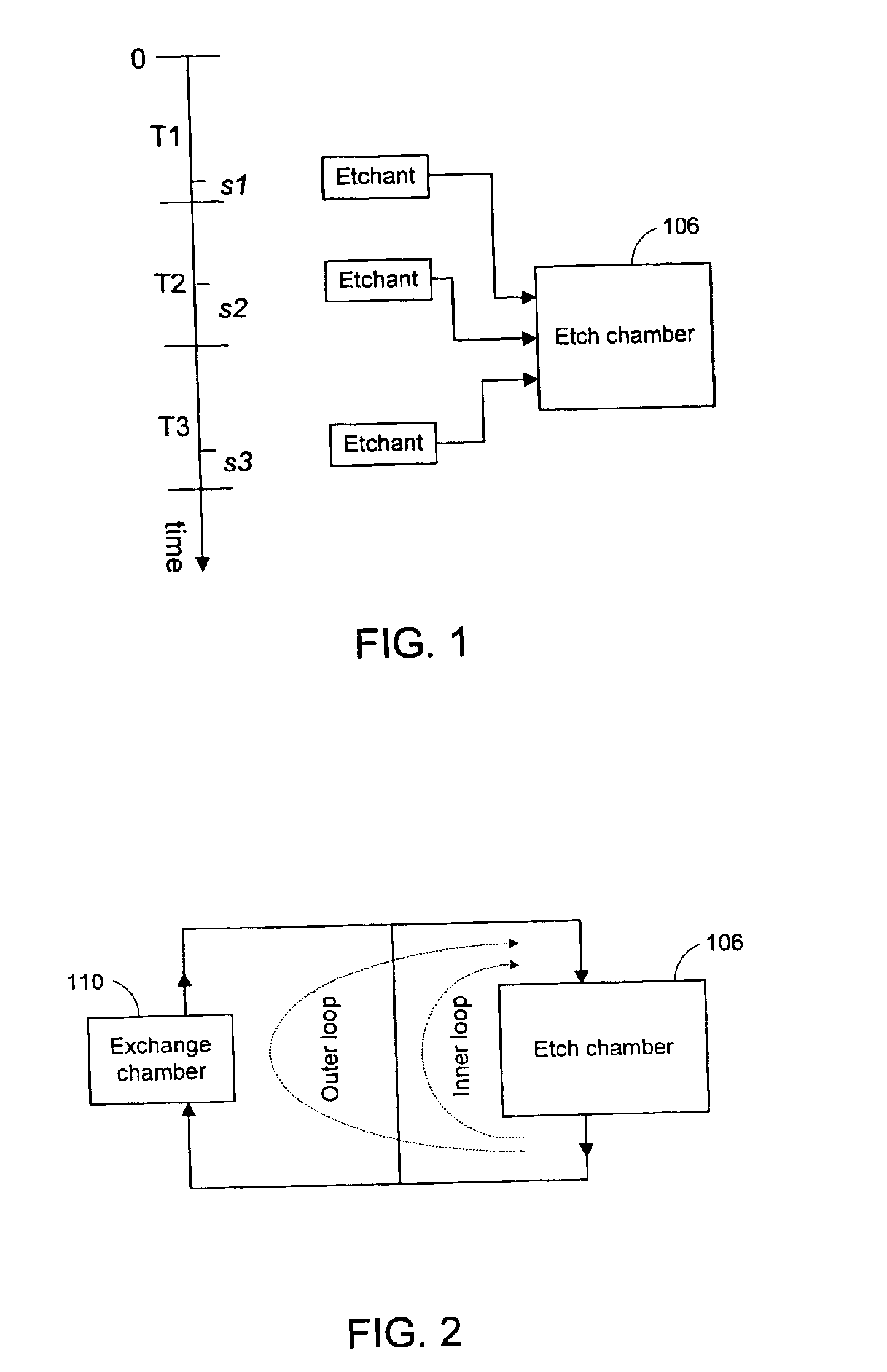
[0018]Referring to FIG. 1, three consecutive feeding cycles T1, T2, and T3 of a sequence of feeding cycles are illustrated along a timeline. Though preferably the same, the time intervals of these feeding cycles (e.g. T1, T2 and T3) are not necessarily the same. During a time slot within each feeding cycle, an amount of selected spontaneous vapor phase etchant recipe is fed into etch chamber 106 that contains the microstructure to be etched. The selected etchant recipe may be only a selected spontaneous vapor phase etchant, such as noble gas halide (e.g. XeF2) or interhalogen (e....


PUM

PropertyMeasurementUnit
total timeaaaaaaaaaa
timeaaaaaaaaaa
timeaaaaaaaaaa

Abstract

The present invention teaches a method and apparatus for removing sacrificial materials in fabrications of microstructures using one or more selected spontaneous vapor phase etchants. The selected etchant is fed into an etch chamber containing the microstructure during each feeding cycle of a sequence of feeding cycles until the sacrificial material of the microstructure is exhausted through the chemical reaction between the etchant and the sacrificial material. Specifically, during a first feeding cycle, a first amount of selected spontaneous vapor phase etchant is fed into the etch chamber. At a second feeding cycle, a second amount of the etchant is fed into the etch chamber. The first amount and the second amount of the selected etchant may or may not be the same. The time duration of the feeding cycles are individually adjustable.

Description

TECHNICAL FIELD OF THE INVENTION[0001]The present invention is related generally to the art of fabrications of microstructures which includes such devices as microelectromechanical systems, semiconductor devices, and, more particularly, to methods and apparatus of non-plasma spontaneous vapor phase etching processes used in the fabrications of the microstructures.BACKGROUND OF THE INVENTION[0002]Sacrificial layers of selected sacrificial materials are commonly used in fabrications of microstructures, such as microelectromechanical systems and semiconductor devices. A typical and pervasively used sacrificial material is amorphous silicon. Once the desired structures of the microstructure are formed, the sacrificial layers are removed by etching. The success of the etching process depends upon the selectivity of the etching process. Performance, uniformity and yield can all be improved with increases in the etch selectivity of the sacrificial layers.[0003]More recently, the etching me...

Claims


Application Information

Patent Timeline
Patent Type & Authority Patents(United States)
IPC IPC(8): C23F1/00G01R31/00H01L21/02H01L21/00H01L21/302H01L21/461B01D
CPCB81C1/00595B81C2201/0132
Inventor SCHAADT, GREGORY P.SHI, HONGQIN
Owner VENTURE LENDING & LEASING IV
Why Eureka
Try Eureka