
Testing a transceiver

a transceiver and transceiver technology, applied in the direction of receiver monitoring, transmission monitoring, instruments, etc., can solve the problems of difficult integration of the presented testing implementation into the transceiver, the complexity of the structure required, and the cost of separate test synthesizers, so as to achieve the effect of less space and easy integration into the transceiver

Inactive Publication Date: 2005-09-06
NOKIA CORP
View PDF17 Cites 27 Cited by
  • Summary
  • Abstract
  • Description
  • Claims
  • Application Information

AI Technical Summary

Benefits of technology

[0005]It is an object of the invention to provide a method and an arrangement implementing the method in such a manner that the testing implementation of the transmitter and receiver can easily be integrated and is economically advantageous. This is achieved with the method for testing a transmitter part and a receiver part in a transceiver, where a signal of the transmitter part is mixed with a mixing signal for generating a signal to be connected to the receiver part. The generated signal is connected to the receiver part and the connected signal is compared with the transmitter part signal to test the transceiver. In this method the mixing signal is generated by connecting a signal generated by means of a signal generator used in the operation of the transmitter part and / or receiver part to at least two signal branches, dividing the signal in the signal branches into at least two signals of different frequencies in the different signal branches, and generating a mixing signal from the signals of different frequencies.
[0008]The solution of the invention does not require a separate test synthesizer to carry out testing. The signal that is divided into at least two signals of different frequencies is generated in a signal generator, which is common to both the transmitter part and the receiver part of the transceiver. Alternatively, if the transmitter part and receiver part both have separate signal generators then the signal is generated in the signal generator of the transmitter part or the receiver part. A test signal generated using the solution of the invention may include some non-ideal features, such as frequency deviations, which alleviate the implementation of the solution of the invention. On account of the above the solution of the invention can more easily be integrated into the transceiver and requires less space than the prior art solutions. The solution of the invention enables the electronics required in testing to be directly integrated into a microcircuit. The solution of the invention is also economically advantageous to implement.

Problems solved by technology

A drawback with the prior art solution is that a separate test synthesizer 110 is required for generating the signal to be mixed with the transmitter part signal.
The separate test synthesizer and the complexity of the structure that is required thereof are economically expensive.
Another drawback with the prior art solution is that it is difficult to integrate the presented testing implementation to the transceiver, which is a result of the difficulty involved with the integration of the loop filter included in the test synthesizer and the voltage oscillator.

Method used


Image

  • Testing a transceiver
  • Testing a transceiver
  • Testing a transceiver

Examples


Embodiment Construction

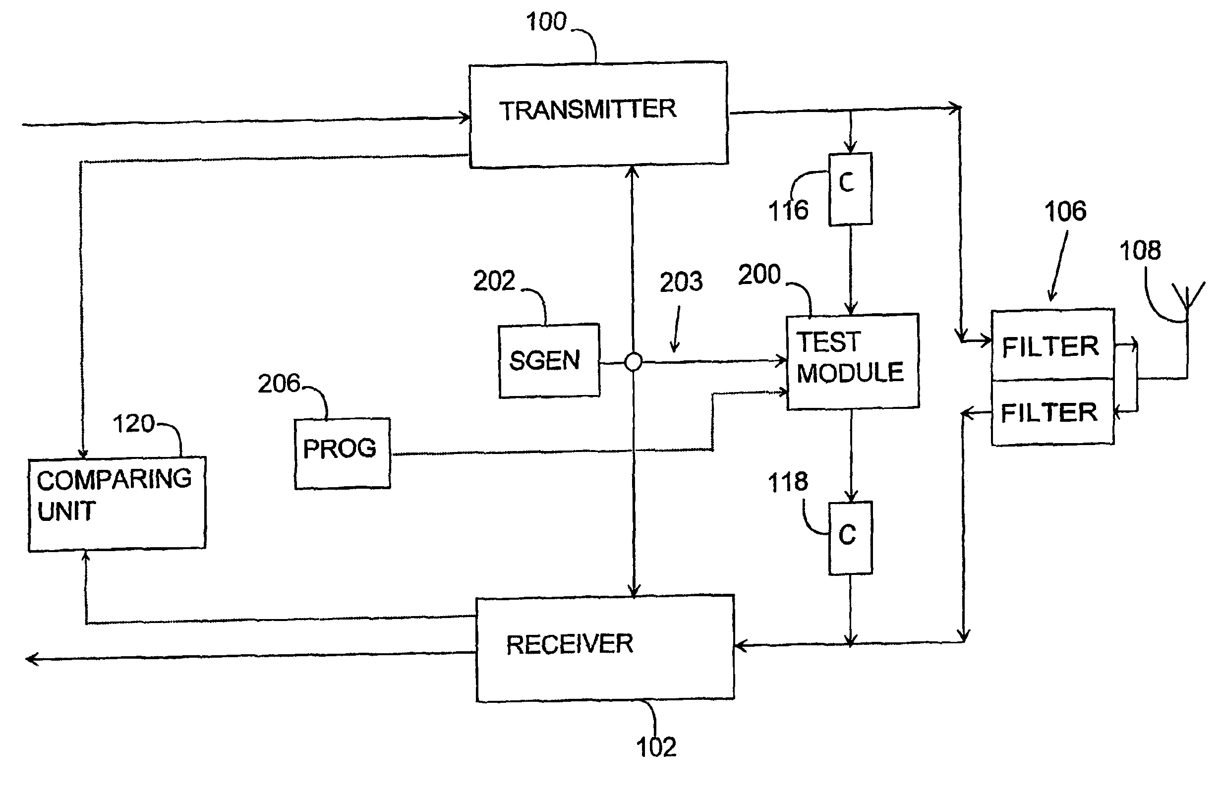
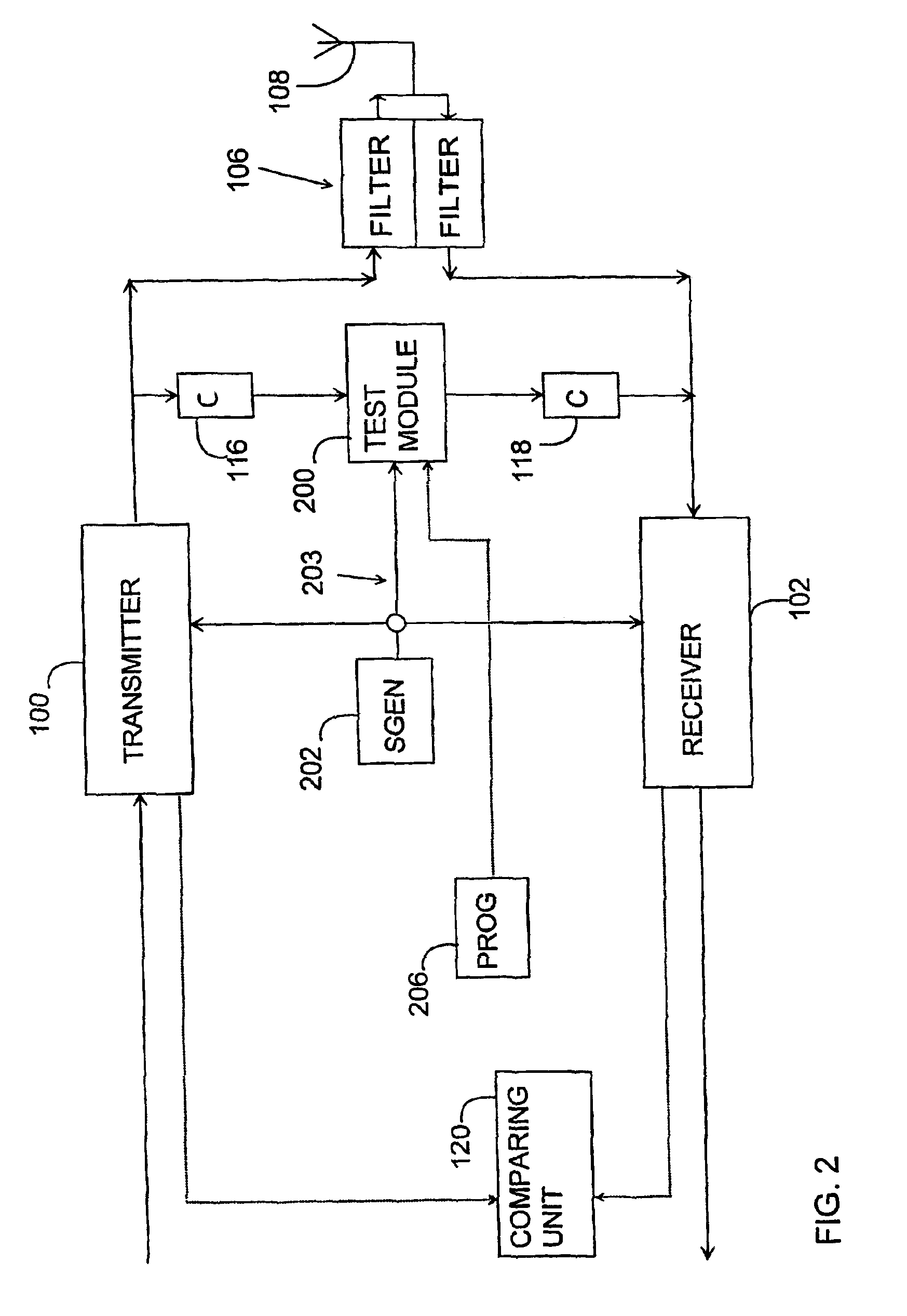
[0020]A transceiver shown in FIG. 2 comprises a transmitter part 100 and a receiver part 102. The transceiver comprises a signal generator 202, which is common to the transmitter part and the receiver part and which is used to generate a desired frequency for the signal to be transmitted in the transmitter part and correspondingly to generate a desired frequency for the signal to be received in the receiver part. The signal generator is typically a synthesizer, for example an RF (Radio Frequencies) synthesizer used in radio frequency applications. In an alternative solution, the transmitter part and the receiver part both include a separate signal generator for generating the signals of desired frequencies.

[0021]FIG. 2 shows an example of the solution of the invention for testing the transceiver, in which the signal generated in the transmitter part 100 is connected through a connection 116 with a desired power to a test unit 200. The signal generator 202 generates a signal, which i...


PUM


Abstract

The invention relates to a method and an arrangement implementing the method for testing a transmitter part and receiver part in a transceiver. A signal in the transmitter part is mixed with a mixing signal for generating a signal to be connected to the receiver part, which generated signal is connected to the receiver part and the connected signal is compared with the transmitter part signal to test the transceiver. The mixing signal is generated by connecting a signal generated by means of a signal generator used in the operation of the transmitter part and / or receiver part to at least two signal branches, dividing the signal in the signal branches into at least two signals of different frequencies in the different signal branches, and generating a mixing signal from the signals of different frequencies.

Description

FIELD OF THE INVENTION[0001]The invention relates to a method and an arrangement implementing the method for testing a transceiver in a radio system.BACKGROUND OF THE INVENTION[0002]Identification of errors in transceiver operation, both in transmitter and receiver operation, constitutes an important part when a reliable data transmission is secured in a radio system. Testing a transceiver in a centralized manner allows the radio system to identify such errors.[0003]FIG. 1 illustrates a prior art solution for testing a transceiver. The transceiver comprises a transmitter part 100, a receiver part 102, a joint synthesizer 104 for the transmitter part and the receiver part, a duplex filter 106 for the signal to be transmitted and received and an antenna 108. Another possible alternative is the one in which the transmitter part and the receiver part both comprise a separate synthesizer. The transceiver also comprises a prior art testing implementation in which a test synthesizer 110 is...

Claims


Application Information

Patent Timeline
IPC IPC(8): H04B1/40H04B17/00
CPCH04B1/40H04B17/20H04B17/19
Inventor HENRIKSSON, MARKKU
Owner NOKIA CORP
Learn More