Optical pickup device that corrects the spot shape of reflected light beams

Inactive Publication Date: 2005-09-06
SONY CORP
View PDF22 Cites 8 Cited by
  • Summary
  • Abstract
  • Description
  • Claims
  • Application Information

AI Technical Summary

Benefits of technology

[0024]In the optical head of the present invention, in which spot shape correction means for correcting the spot shape of the reflected light beam is provided between the objective lens and the light detecting means to correct the spot shape of palt or all of the spots formed by the reflected light beam on the photodetector means, no branching prism is required, while only one light detecting means suffices, with the result that the number of component parts and adjustment steps can be diminished and the adjustment process for the light detecting means may be simplified, while the reduction in size and cost may be achieved. Thus, reduction in the number of component parts or adjustment steps, reduction in size and cost of the optical head and stabilized

Problems solved by technology

However, in a optical recording medium of recording information signals by the land and groove recording system, it has been ascertained that the phenomenon termed “tracking interference” as later explained occurs in case of employing the aforementioned astigmatic method for detecting the focussing errors, thus giving rise to a noise termed “track traversing noise”.
So, each time a beam spot is moved from the land to the groove on the optical disc, or vice versa, the objective lens is reciprocated between the positions XL and XG, thus producing the track traversing noise.
This noise is responsible for a v

Method used


Image

  • Optical pickup device that corrects the spot shape of reflected light beams
  • Optical pickup device that corrects the spot shape of reflected light beams
  • Optical pickup device that corrects the spot shape of reflected light beams

Examples


Embodiment Construction

[0058]Referring to the drawings, an optical head according to the present invention, a light receiving / emitting device used on this optical head and an optical recording medium recording and / or reproducing apparatus employing the optical head according to the present invention will be explained in detail.

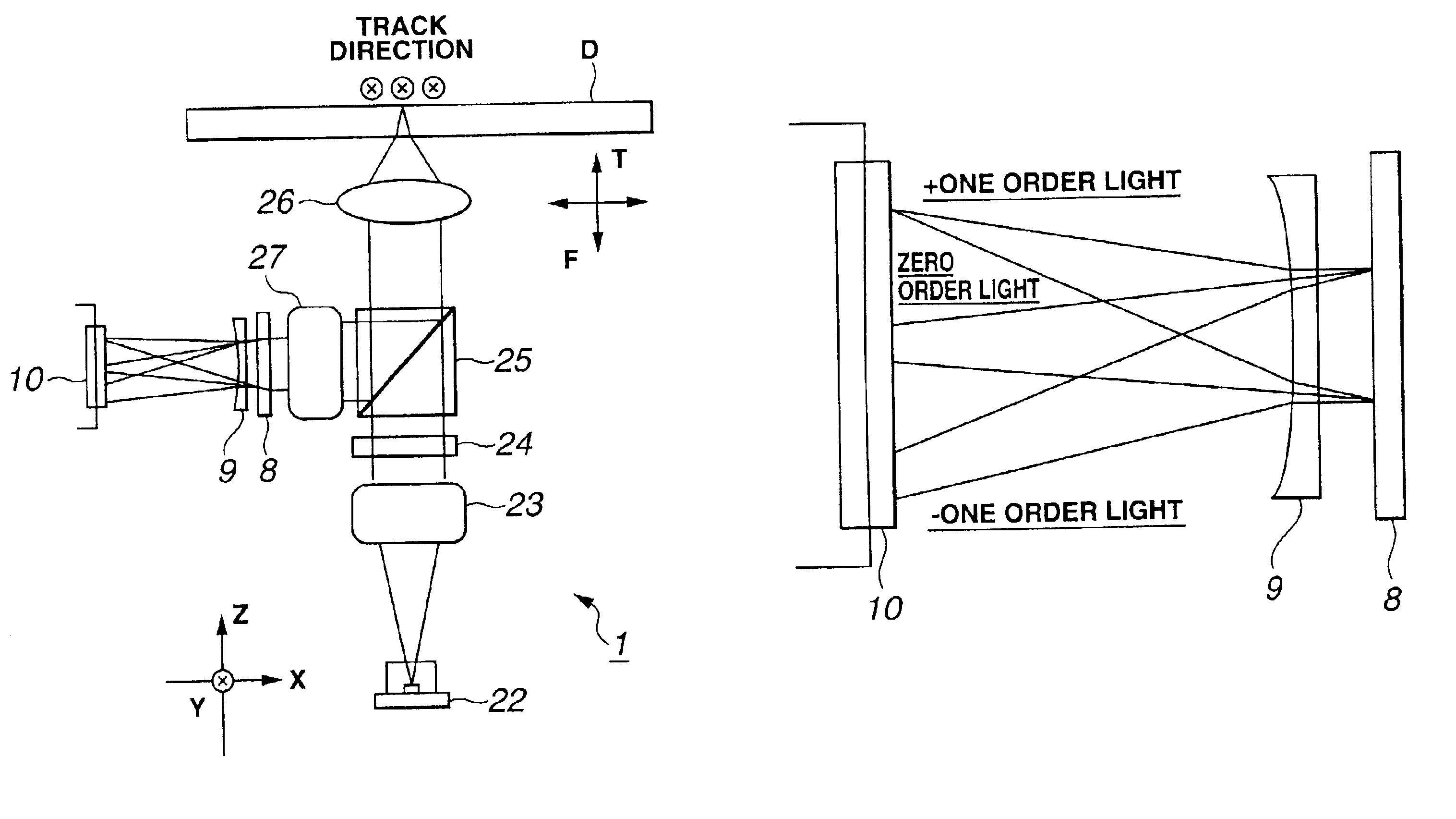
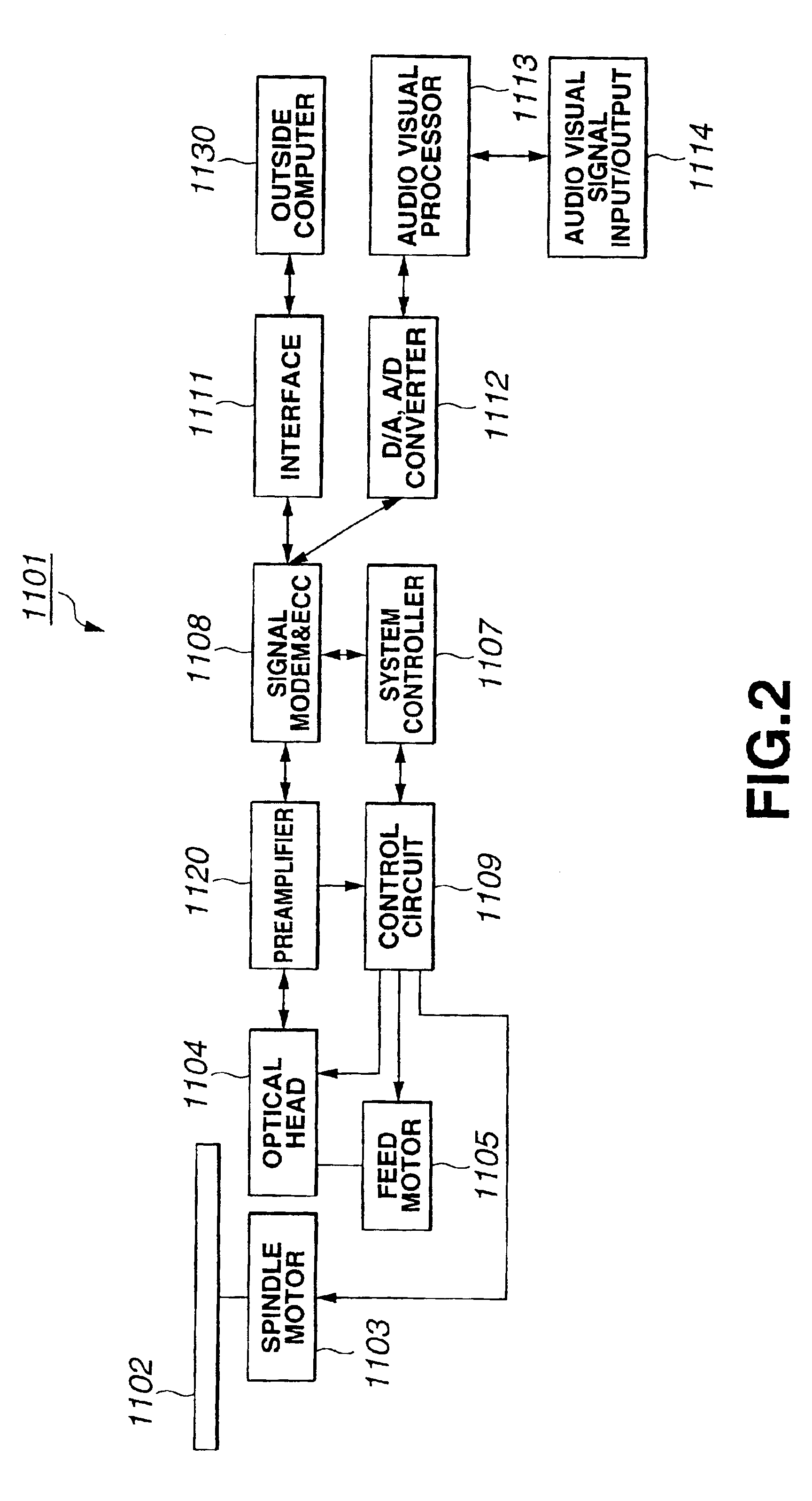
[0059]FIG. 2 is a block diagram of an optical disc recording and / or reproducing apparatus employing, as a recording medium, an optical head having a built-in optical head employing a light receiving / emitting device according to the present invention.

[0060]The optical disc recording and / or reproducing apparatus shown in FIG. 2 is a as typical optical recording medium recording and / or reproducing apparatus capable of loading thereon a light receiving / emitting device according to the present invention as later explained and an optical head employing this light receiving / emitting device. In the following description, it is assumed that the optical recording medium recording and / or repro...


PUM


Abstract

An optical head in which focussing error is detected by a spot size method used for recording and/or reproducing information signals on or from an optical disc. The optical head includes a unit for correcting the spot shape between the objective lens and a photodetector device. The spot shape correcting unit corrects part or all of light spots formed on the photodetector by a light beam reflected back by the optical disc so that the spot diameter in a direction traversing a track on the optical disc will be larger than the spot diameter along the track.

Description

TECHNICAL FIELD[0001]This invention relates to an optical recording and / or reproducing apparatus, such as an optical disc apparatus recording and / or reproducing information signals, using an optical recording medium, such as an optical disc, an optical bead used in the optical recording and / or reproducing apparatus, and to a light receiving / emitting device used in the optical head.BACKGROUND ART[0002]A wide variety of optical information recording and / or reproducing apparatus optically recording and / or reproducing the information, using an optical information recording medium, such as an optical disc, are currently in use. In particular, the recording and / or reproducing apparatus for an optical recording medium, employing the optical disc as the recording medium, is used extensively and researches into a higher recording density of the optical disc are now underway.[0003]For example, as a replay-only optical recording and / or reproducing apparatus, such an optical disc apparatus, is ...

Claims


Application Information

Patent Timeline
IPC IPC(8): G11B11/105G11B11/00G11B7/125G11B7/007G11B7/135G11B7/09G11B7/12G11B7/13G11B7/1372G11B7/1353
CPCG11B7/00718G11B7/0912G11B7/123G11B7/131G11B7/133G11B7/1353G11B7/1356G11B7/1359G11B7/1369G11B7/1378G11B7/1381G11B7/13927G11B7/1398G11B11/10543G11B11/10576G11B7/0917G11B7/13G11B7/1374G11B7/1395G11B2220/2537
Inventor NISHI, NORIAKI
Owner SONY CORP
Why Eureka
Try Eureka