Projection Lens for EUV Microlithography, Film Element and Method for Producing a Projection Lens Comprising a Film Element

Active Publication Date: 2014-11-27
CARL ZEISS SMT GMBH
View PDF11 Cites 11 Cited by
  • Summary
  • Abstract
  • Description
  • Claims
  • Application Information

AI Technical Summary

Benefits of technology

[0008]One object of the invention is to simplify the adjustment process for EUV projection lenses during production. A further object is to simplify a subsequent correct

Problems solved by technology

Radiation from the extreme ultraviolet range (EUV radiation) cannot be sufficiently focused or guided with the aid of refractive optical elements, since the short wavelengths are greatly absorbed by the known optical materials that are transparent at higher wavelengths, or other materials.
Deviations of the wavefront from a wavefront predefined by the specification can lead to imaging aberrations that cannot be afforded tolerance.
What is problematic in this case is, inter alia, that the true state of the optical elements (in particular owing to the coating) can be measured sufficiently precisely only in the assembled state at the working wavelength (e.g. 13.5 nm).
In this stage, often all that remains for a subsequent correction is very complex partial disassembly of the projection lens in order to rework

Method used


Image

  • Projection Lens for EUV Microlithography, Film Element and Method for Producing a Projection Lens Comprising a Film Element
  • Projection Lens for EUV Microlithography, Film Element and Method for Producing a Projection Lens Comprising a Film Element
  • Projection Lens for EUV Microlithography, Film Element and Method for Producing a Projection Lens Comprising a Film Element

Examples


Example

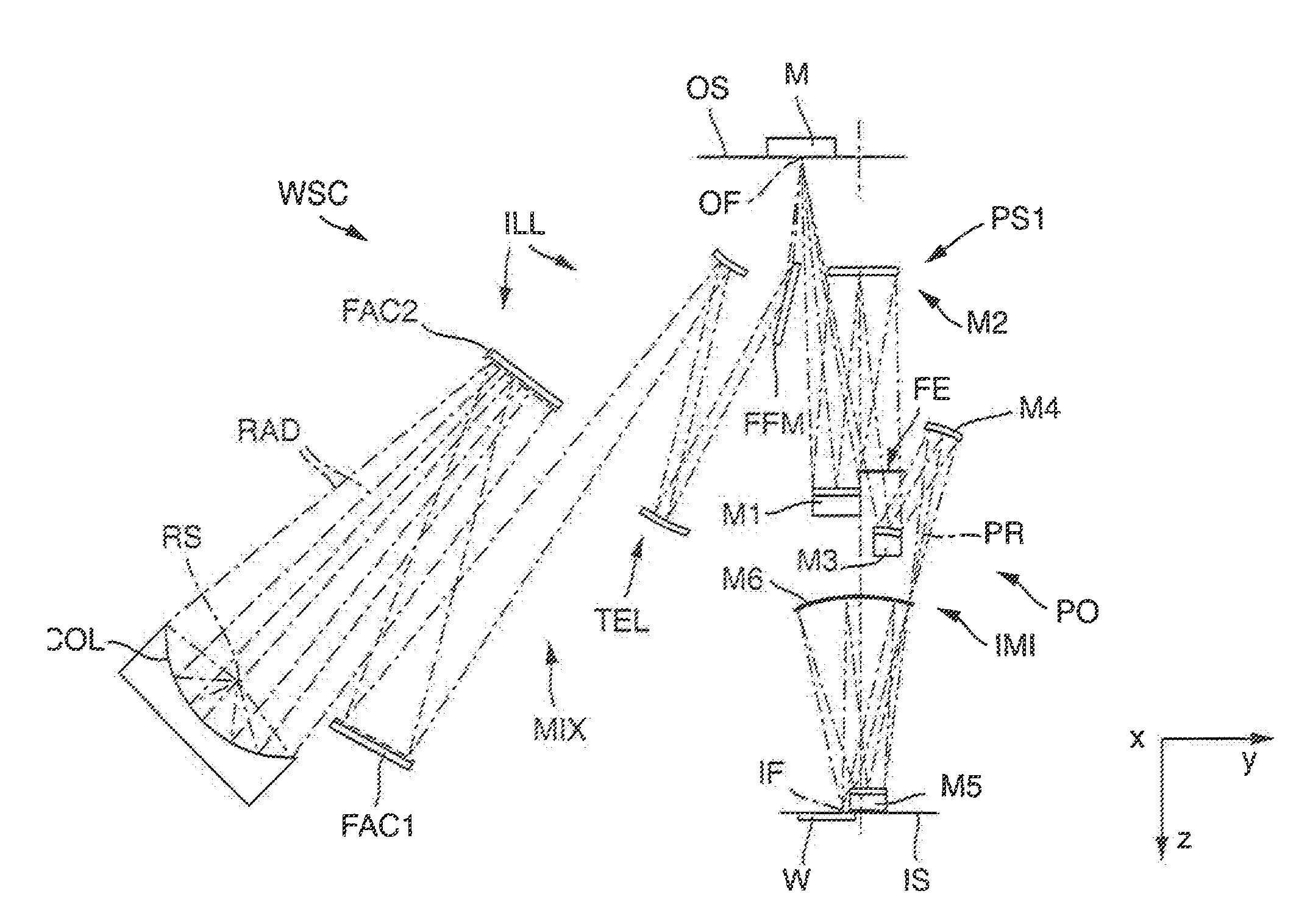
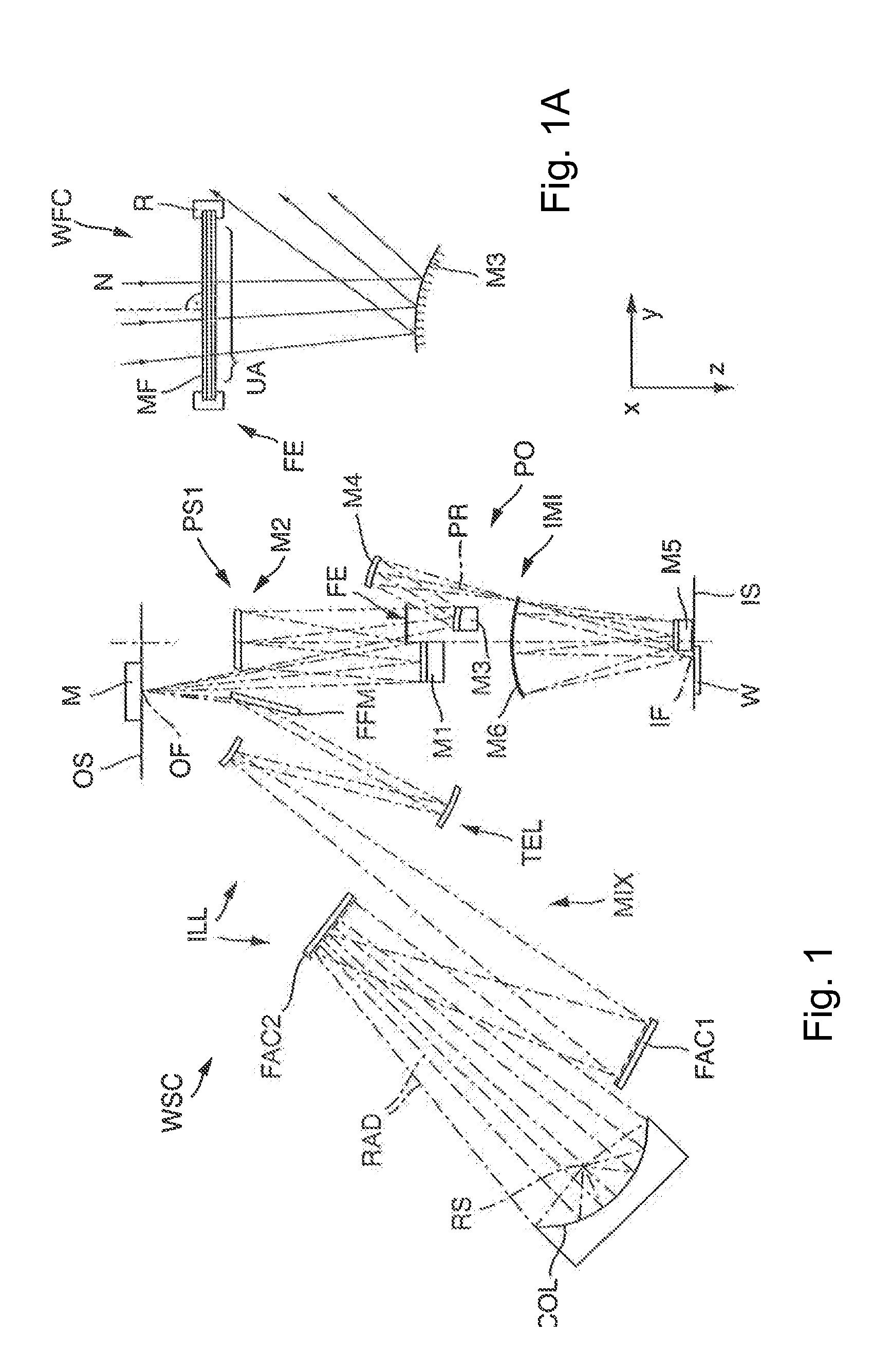
[0102]FIG. 1 shows optical components of an EUV microlithography projection exposure apparatus WSC in accordance with one embodiment of the invention. The EUV microlithography projection exposure apparatus serves for the exposure of a radiation-sensitive substrate W, arranged in the region of an image plane IS of a projection lens PO, with at least one image of a pattern of a reflective patterning device or mask M, said pattern being arranged in the region of an object plane OS of the projection lens.

[0103]In order to facilitate the description, a Cartesian xyz coordinate system is specified, from which the respective positional relationship of the components illustrated in the figures is evident. The projection exposure apparatus WSC is of the scanner type. The mask M and the substrate are moved synchronously in the y-direction during the operation of the projection exposure apparatus, and thereby scanned.

[0104]The apparatus is operated with the radiation of a primary radiation sou...


PUM

PropertyMeasurementUnit
Thicknessaaaaaaaaaa
Thicknessaaaaaaaaaa
Angleaaaaaaaaaa

Abstract

A film element of an EUV-transmitting wavefront correction device is arranged in a beam path and includes a first layer of first layer material having a first complex refractive index n1=(1−δ1)+iβ1, with a first optical layer thickness, which varies locally over the used region in accordance with a first layer thickness profile, and a second layer of second layer material having a second complex refractive index n2=(1−δ2)+iβ2, with a second optical layer thickness, which varies locally over the used region in accordance with a second layer thickness profile. The first and second layer thickness profiles differ. The deviation δ1 of the real part of the first refractive index from 1 is large relative to the absorption coefficient β1 of the first layer material and the deviation δ2 of the real part of the second refractive index from 1 is small relative to the absorption coefficient β2 of the second layer material.

Description

[0001]This is a Continuation of International Application PCT / 2013 / 000382, with an international filing date of Feb. 8, 2013, which was published under PCT Article 21(2) in English, and the complete disclosure of which, is incorporated into this application by reference.TECHNICAL FIELD AND BACKGROUND[0002]The invention relates to a projection lens for imaging a pattern arranged in an object plane of the projection lens into an image plane of the projection lens with electromagnetic radiation having a working wavelength λ from the extreme ultraviolet range (EUV). Furthermore, the invention relates to a film element provided, in particular, for use in such a projection lens, and to a method for producing a projection lens containing a film element.[0003]Nowadays predominantly microlithographic projection exposure methods are used for producing semiconductor components and other finely structured components. In this case, use is made of masks (reticles) or other patterning devices whic...

Claims


Application Information

Patent Timeline
IPC IPC(8): G02B17/08
CPCG02B17/0896G02B17/0892G03F7/70191G03F7/70233G03F7/70316G21K1/062B82Y10/00Y10T29/49826
Inventor BITTNER, BORISWABRA, NORBERTSCHNEIDER, SONJASCHNEIDER, RICARDAWAGNER, HENDRIKWALD, CHRISTIANILIEW, RUMENSCHICKETANZ, THOMASGRUNER, TORALFPAULS, WALTERSCHMIDT, HOLGER
Owner CARL ZEISS SMT GMBH
Why Eureka
Try Eureka