Apparatus and method for a lift seat

a technology for lifting seats and apparatuses, applied in medical science, nursing beds, ambulance services, etc., can solve the problems of time-consuming measurements, dirty seats at patient lifting devices, and inconvenient cleaning

Inactive Publication Date: 2005-09-13
MICHAEL M TIMOTHY
View PDF11 Cites 30 Cited by
  • Summary
  • Abstract
  • Description
  • Claims
  • Application Information

AI Technical Summary

Benefits of technology

[0012]The present invention discloses a lift seat which comprises a lifting column mounted upon a wheeled base frame capable of being rolled on an underlying surface. Attached to the lifting column is a seat support and a seat with a rigid bottom. The lifting column contains an acme screw mechanism powered by an electric motor equipped with a handheld motor control device which comprises the means for moving the seat vertically up and down the lifting column from a lowest position wherein the seat is substantially resting on the underlying surface to a highest position which is substantially higher than a normal seating position. Alternately, the lifting means may comprise a manual crank. The present invention, therefore, provides a means by which a person could extract themselves from a position upon the floor and raise themselves to a normal seating height or to a near standing height. Alternately, the present invention provides a means whereby a person can lower themselves to the floor.
[0013]An object of the present invention is to provide a lifting seat which will raise the physically challenged occupant from the floor to a standard seating height or to a near standing height making standing easier for the occupant. Another object is to provide a liking seat which can be operated by a solo user and occupant or by a frail assistant. A further object is to provide a lifting seat which will allow the physically challenged user to easily self load into the lifting seat.

Problems solved by technology

Since the seats at patient-lifting devices often become very dirty, they need to be cleaned in special cleaning devices, so called decontamination devices.
However, the present seats are not suitable for cleaning in cleaning devices of this type and time-consuming measurements are required to loosen and reengage the seats.

Method used


Image

  • Apparatus and method for a lift seat
  • Apparatus and method for a lift seat

Examples


Embodiment Construction

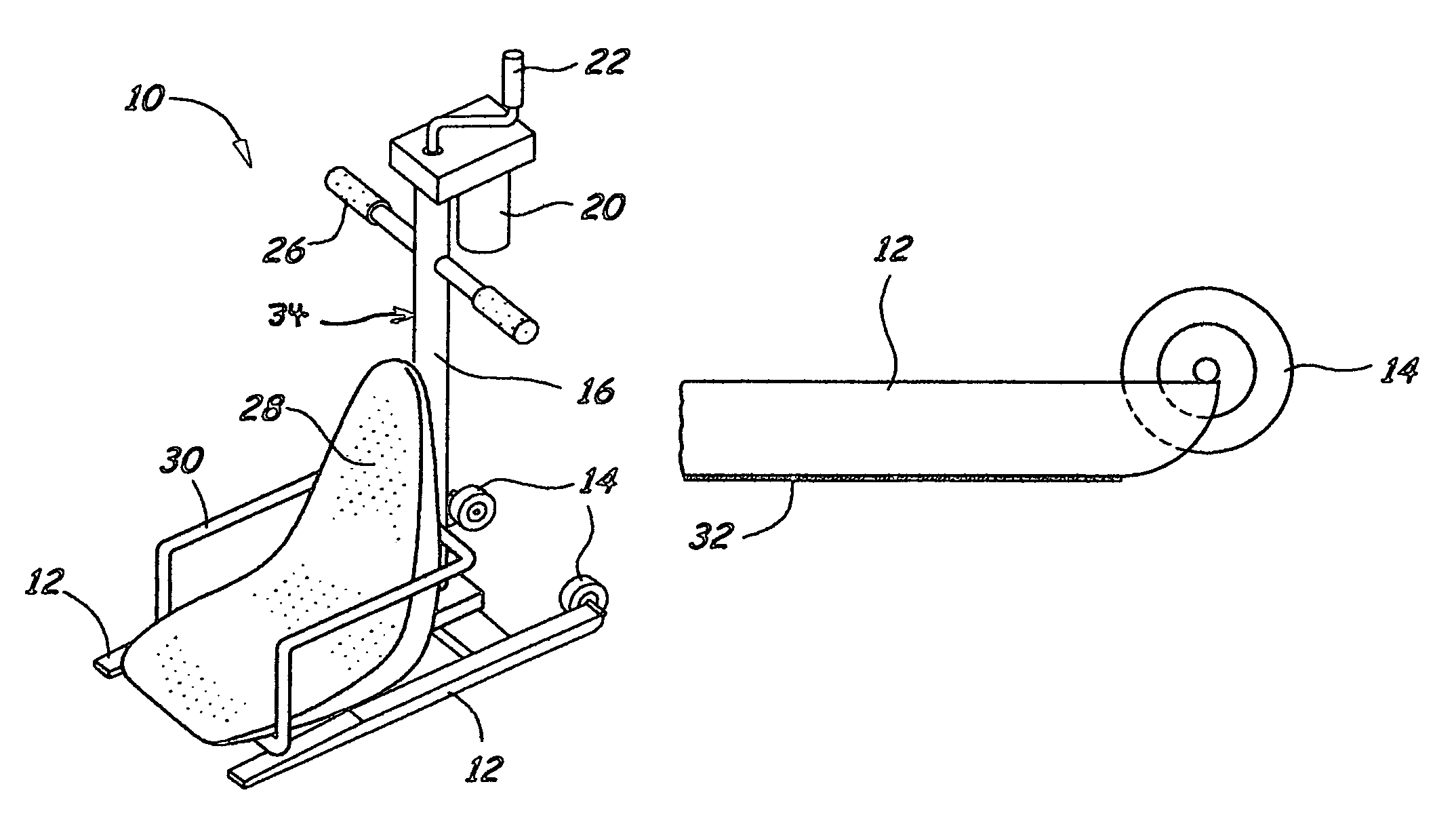
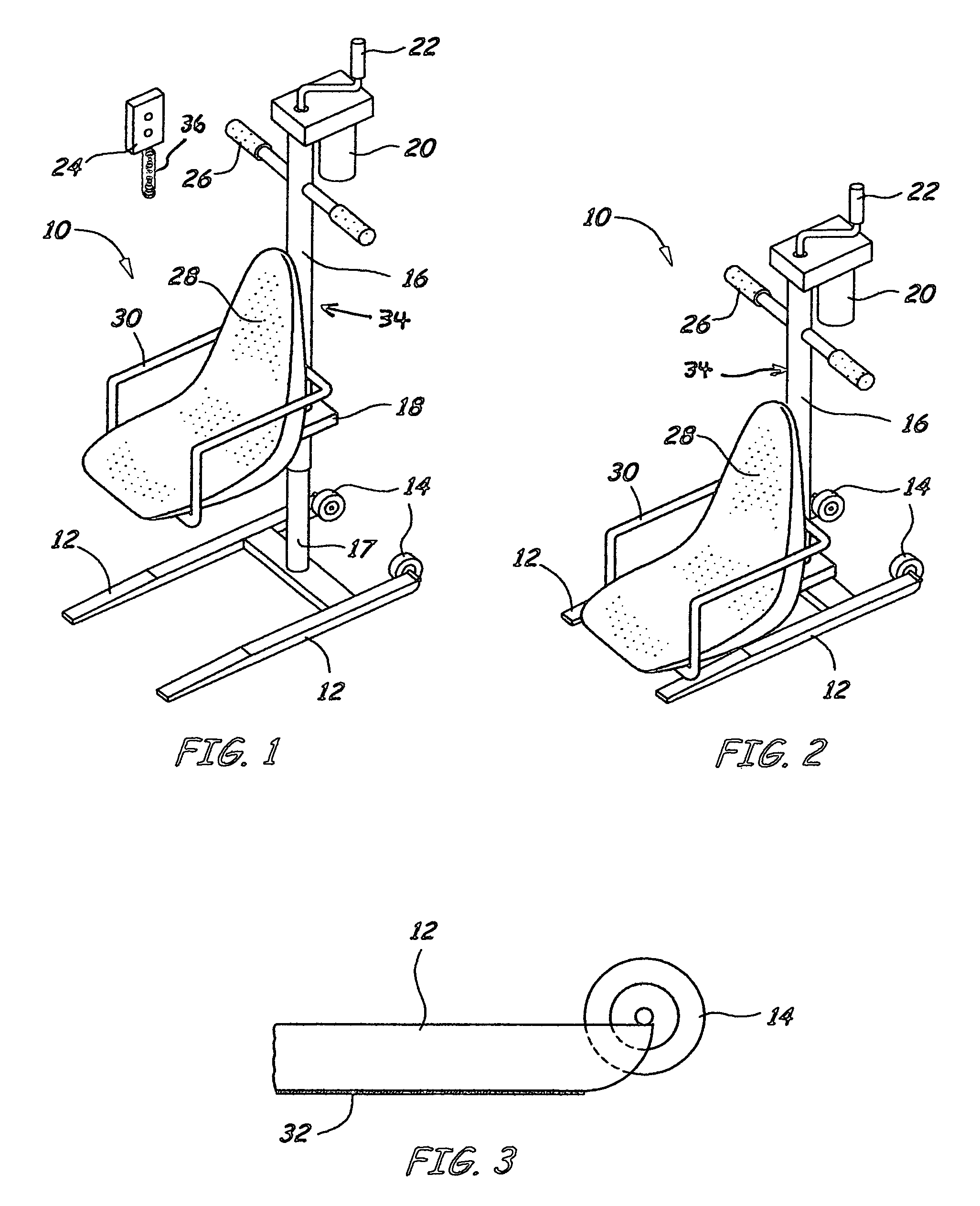
[0037]Turning now descriptively to the drawings, in which similar reference characters denote similar elements throughout the several views wherein the Figures illustrate the present invention wherein a lift seat is disclosed.

[0038]Turning to FIG. 1, shown therein is an isometric view of the present invention 10. The base 12 is formed of steel tubing and has a front in the direction of the seat and a rear. At the rear are positioned a pair of wheels 14 slightly elevated so as not to be in contact with the floor except when the unit 10 is tilted backwardly as best shown in FIG. 3. The lifting column comprises an inner column 17 which is bolted or welded to base frame 12 and an outer column 16 to which the seat support frame 18 and handle 26 are attached. The outer column 16 is raised or lowered by an internal hoisting gear 34 which may be an acme screw or similar hoisting gear comprising a nut and bolt combination traversing the length of the column and which is turned by an electric...


PUM


Abstract

The present invention discloses a portable lift seat to raise or lower a physically challenged user from a position on the floor to a standard height seated position or to a near standing position or vice versa. The lifting and lowering mechanism includes a seat with a rigid bottom supported by a seat support means which is attached to a lifting column standing upon a base fame. The lifting column is powered by an electric motor which may be controlled with a handheld control device. Alternatively, the lifting column may be powered by a manual crank. The base unit is equipped with wheels which engage for portability.

Description

BACKGROUND OF THE INVENTION[0001]1. Field of the Invention[0002]The present invention relates generally to lift seats and, more particularly, to an improved lift seat which assists a user in rising from and descending to a position on the floor.[0003]2. Description of the Prior Art[0004]Lift seats have been described in the prior art; however, none of the prior art devices disclose the unique features of the present invention.[0005]In U.S. Pat. No. 6,430,761, dated Aug. 13, 2002, Brandorff, et al., disclosed an improved portable patient transfer device comprising a small wheeled base having a vertically disposed telescoping lifting column extending upwardly therefrom. A patient support means extends from the column to support the patient. A crank, accessible to both patient and attendant, is used to raise and lower the lifting column for transfer between surfaces with different heights, such as beds, wheelchairs, and car seats. The lift may be closed and temporarily attached to a wh...

Claims


Application Information

Patent Timeline
Patent Type & Authority Patents(United States)
IPC IPC(8): A61G7/10
CPCA61G7/1011A61G7/1019A61G2200/34A61G2203/12
Inventor MICHAEL, M. TIMOTHY
Owner MICHAEL M TIMOTHY
Why Eureka
Try Eureka