
Bed frame

a bed frame and frame technology, applied in the field of bed frames, can solve the problems of high shipping costs, relatively labor-intensive and costly bed frame manufacturing, and achieve the effect of preventing looseness and accidental disengagement, sagging, and possible collapse of the bed fram

Inactive Publication Date: 2005-09-13
SCHUMAN ETHAN JOEL +1
View PDF11 Cites 16 Cited by
  • Summary
  • Abstract
  • Description
  • Claims
  • Application Information

AI Technical Summary

Benefits of technology

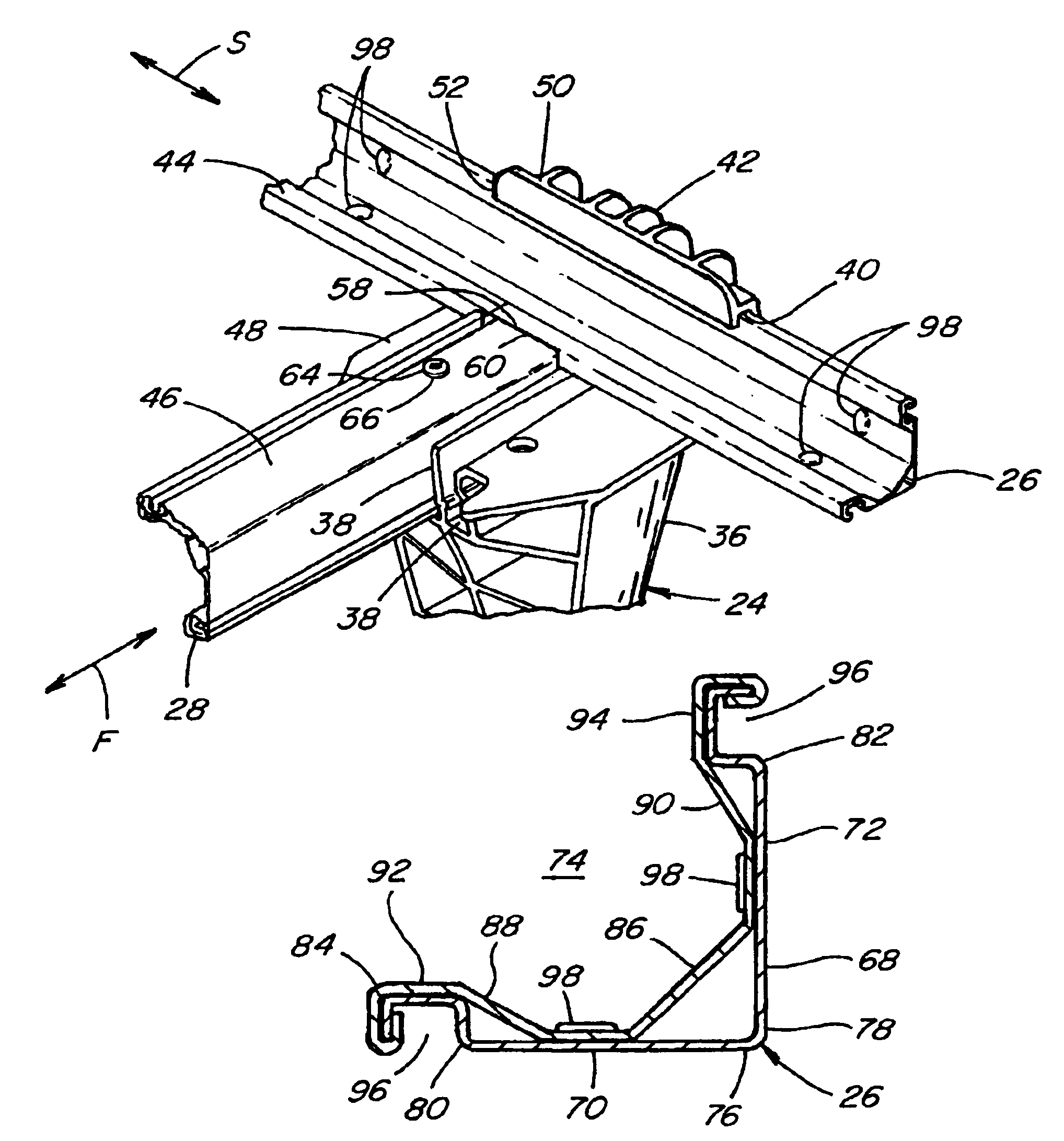
[0007]Importantly, each of the rails is locked into position on the respective foot to form a rigid assembly or structure, and so as to prevent looseness and accidental disengagement, sagging, and possible collapse of the bed frame as a result. According to a preferred embodiment, at least one locking element is provided for lockingly holding one of the rails in its respective receptacle or slot, in a position so as to bear against or retain or lock in the other of the rails, such that the rails associated with each foot are effectively interlocked together, providing sought after rigidity and strength. The receptacles or slots are also preferably positioned such that downward forces exerted by the box spring and mattress or other bedding, loads carried thereon, as well as some other anticipated additional loads, such as exerted by persons jumping onto the bed, will be directed, at least in some part, to hold the assembled members together.

Problems solved by technology

This high weight is a disadvantage as it results in higher than desired shipping costs.
Another shortcoming is that manufacture of the bed frames is relatively labor intensive and costly, due in at least large part to the requirement of cutting, drilling, and connecting together the parts thereof.

Method used


Image

  • Bed frame
  • Bed frame
  • Bed frame

Examples


Embodiment Construction

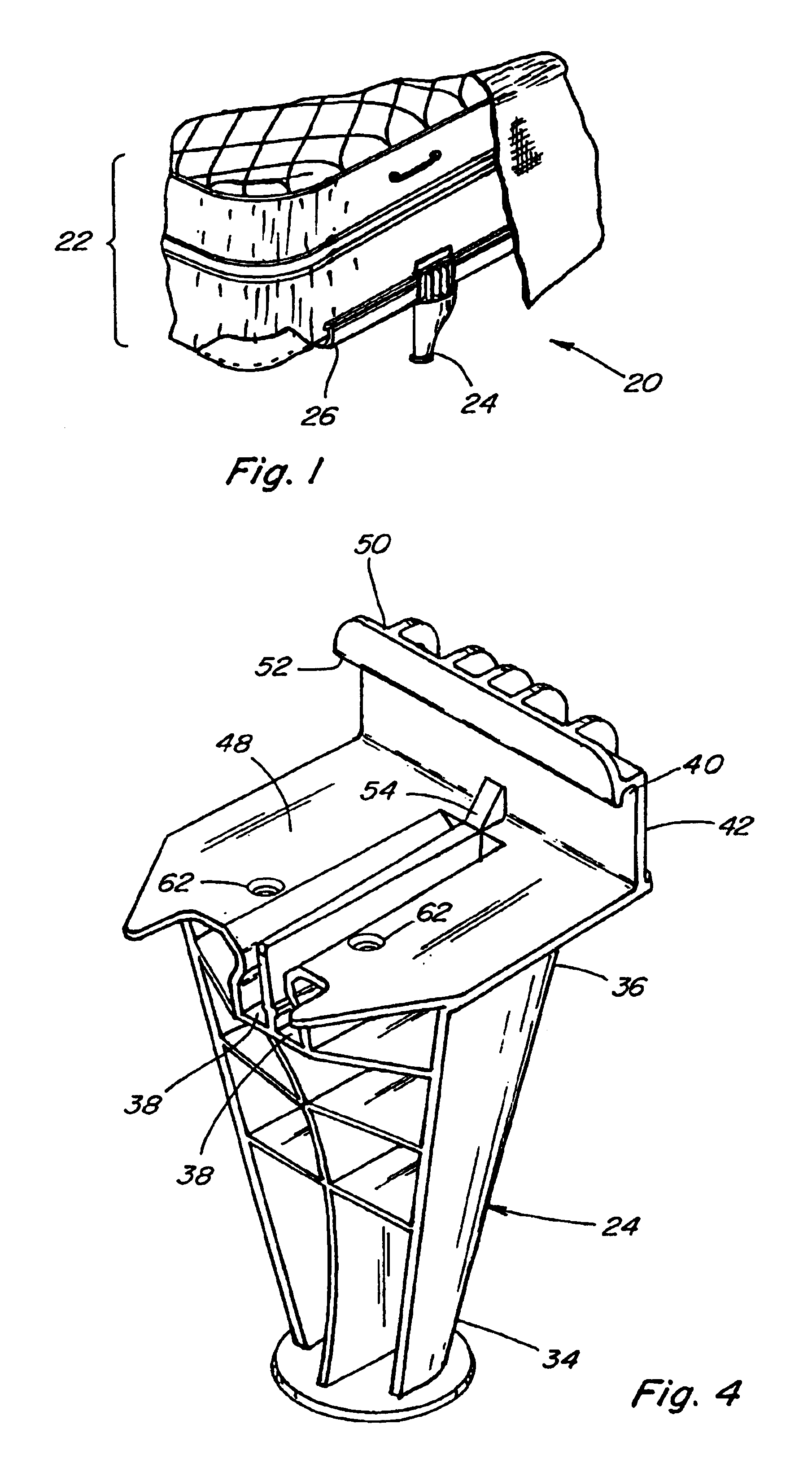
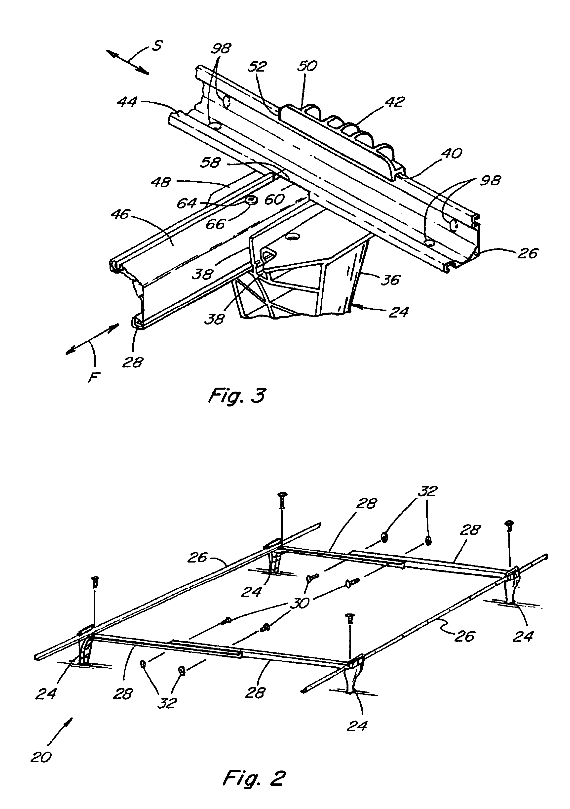
[0024]Referring now to the drawings, FIG. 1 shows aspects of a bed frame 20 constructed and operable according to the teachings of the present invention, supporting a conventional box spring and mattress set 22 in a generally horizontal, flat orientation, one atop the other, in the well known manner. Referring also to FIG. 2, bed frame 20 generally includes a plurality of feet 24, a pair of side rails 26, and two pairs of cross rails 28, that can be assembled to form a rectangular platform, such as shown, and as defined by feet 24 at the corners of the rectangle which connect side rails 26 with cross rails 28 along the sides of the rectangle, respectively. Each pair of cross rails 28 preferably can be assembled so as to have a length corresponding to the width of a particular box spring and mattress set 22, by suitable fasteners, connectors or pins, as represented by bolts 30 which are inserted through selected ones of holes at various locations through rails 28, and are secured in ...


PUM


Abstract

A bed frame assembly for supporting a bed in a substantially flat manner above a floor including interlocking elongate rails and feet for forming a rectangular, flat platform, each of the feet including an upper portion defining a receptacle oriented in a first direction for receiving a longitudinal end a portion of a first of the rails, and a second receptacle oriented in a second direction at about a 90 degree angle to the first direction for receiving a portion of a second of the rails, such that when received in the receptacles, respectively, the first and second rails being in abutting interlocking relation and extend in the first and second directions defining the platform, and elements cooperatively engageable with each of the feet, respectively, for holding the rails in the abutting relation.

Description

TECHNICAL FIELD[0001]This invention relates generally to bed frames for supporting box spring and mattress sets, and more particularly, to a bed frame preferably including roll-form metal rails which provide suitable torsional strength for anticipated loading conditions, and a plurality of interchangeable feet for supporting and connecting the bed rails, all which can be provided in a compact, lightweight kit for economical storage and transport, and which can be easily assembled into a strong, rigid structure.BACKGROUND ART[0002]Bed frames for supporting box springs and mattresses are well known. One popular type of such bed frames utilizes opposing L shape solid steel side rails foldably connected to L shape steel cross rail sections, the cross rail sections associated with the respective side rails being connectable together to form the bed frame. The side rails typically include downwardly extending feet or legs riveted or otherwise attached and on which the bed frame is support...

Claims


Application Information

Patent Timeline
IPC IPC(8): A47C19/04A47C19/00
CPCA47C19/024A47C19/04
Inventor SCHUMAN, ETHAN JOELKOENEKER, WILLIAM VERNON
Owner SCHUMAN ETHAN JOEL
Learn More