
Methods of fabricating a thin-wall expandable well screen assembly

a well screen and expansion plate technology, applied in the direction of filtration separation, well accessories, separation processes, etc., can solve the problems of unsuitable for this purpose, inability to provide any radial support for an unconsolidated formation, and additional expense and loss of revenue, so as to facilitate the radial expansion facilitate the fabrication of the well screen, and facilitate the effect of radial expansion

Inactive Publication Date: 2005-09-13
HALLIBURTON ENERGY SERVICES INC
View PDF61 Cites 43 Cited by
  • Summary
  • Abstract
  • Description
  • Claims
  • Application Information

AI Technical Summary

Benefits of technology

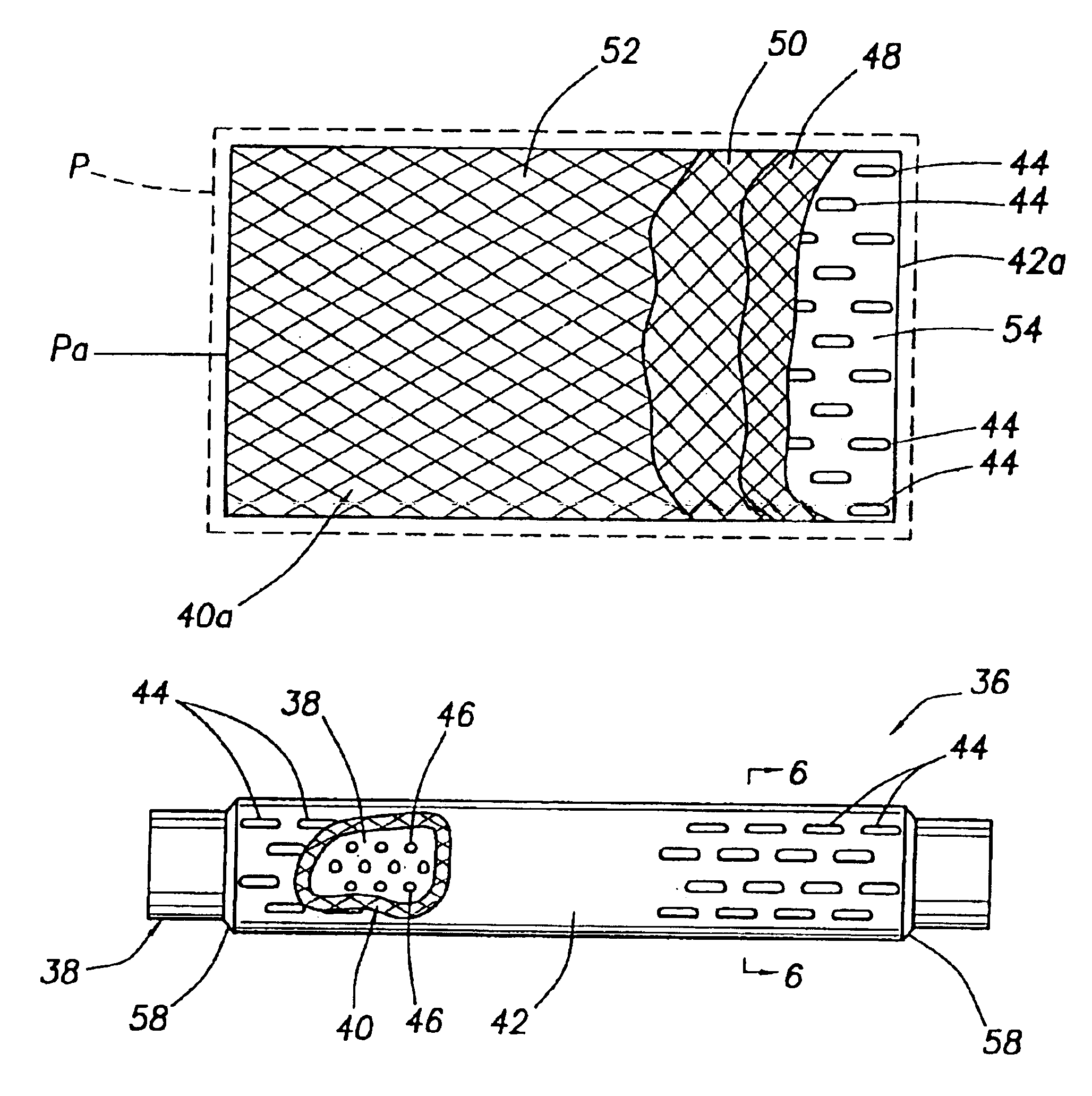
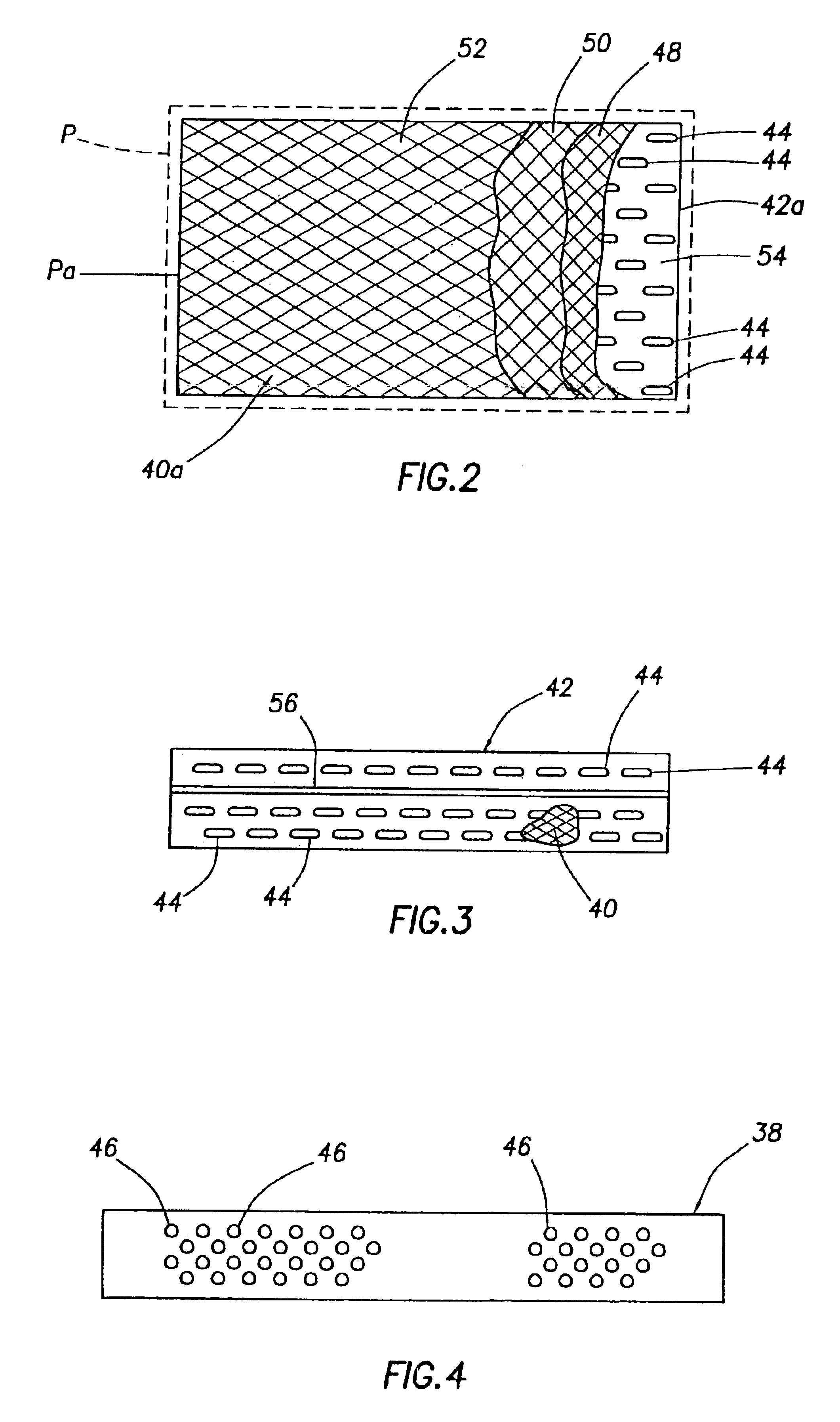
[0008]According to an aspect of the invention, the well screen includes a perforated tubular base pipe coaxially circumscribed by a specially designed thin-walled tubular filter structure anchored to the base pipe and defined by a perforated tubular outer protective shroud having a tubular filter media sheet secured directly to its inner side surface. The construction of the filter structure facilitates the radial expansion of the well screen, provides it with a greater central flow area for a given maximum outer well screen diameter, simplifies the fabrication of the well screen, and reduces the fabrication cost of the well screen.

Problems solved by technology

Unfortunately, without any radial support the unconsolidated formation would likely collapse into the wellbore, causing additional expense and loss of revenue.
Conventional nonexpandable well screens must necessarily be smaller than the wellbore in order to be conveyed therethrough, and so they are incapable of providing any radial support for an unconsolidated formation.
Previously proposed expandable well screens have associated therewith several problems, limitations and disadvantages.
For example, they are typically not designed for contacting and providing radial support for a formation, and are thus unsuited for this purpose.
The relative structural complexity of this previously proposed expandable well screen assembly, and the necessity of using multiple steps to fabricate it, undesirably increases its fabrication cost.
Moreover, since the assembly portion outwardly circumscribing a perforated base pipe portion of the well screen has several layers, the maximum permissible unexpanded diameter of the base pipe is undesirably reduced due to the necessity of limiting the outer diameter of the well screen assembly to a maximum value determined by limiting well dimensions.
Due to this reduced unexpanded diameter of the base pipe, operational expansion thereof undesirably increases the expansion stresses thereon and reduces the maximum available expanded diameter thereof.

Method used


Image

  • Methods of fabricating a thin-wall expandable well screen assembly
  • Methods of fabricating a thin-wall expandable well screen assembly
  • Methods of fabricating a thin-wall expandable well screen assembly

Examples


Embodiment Construction

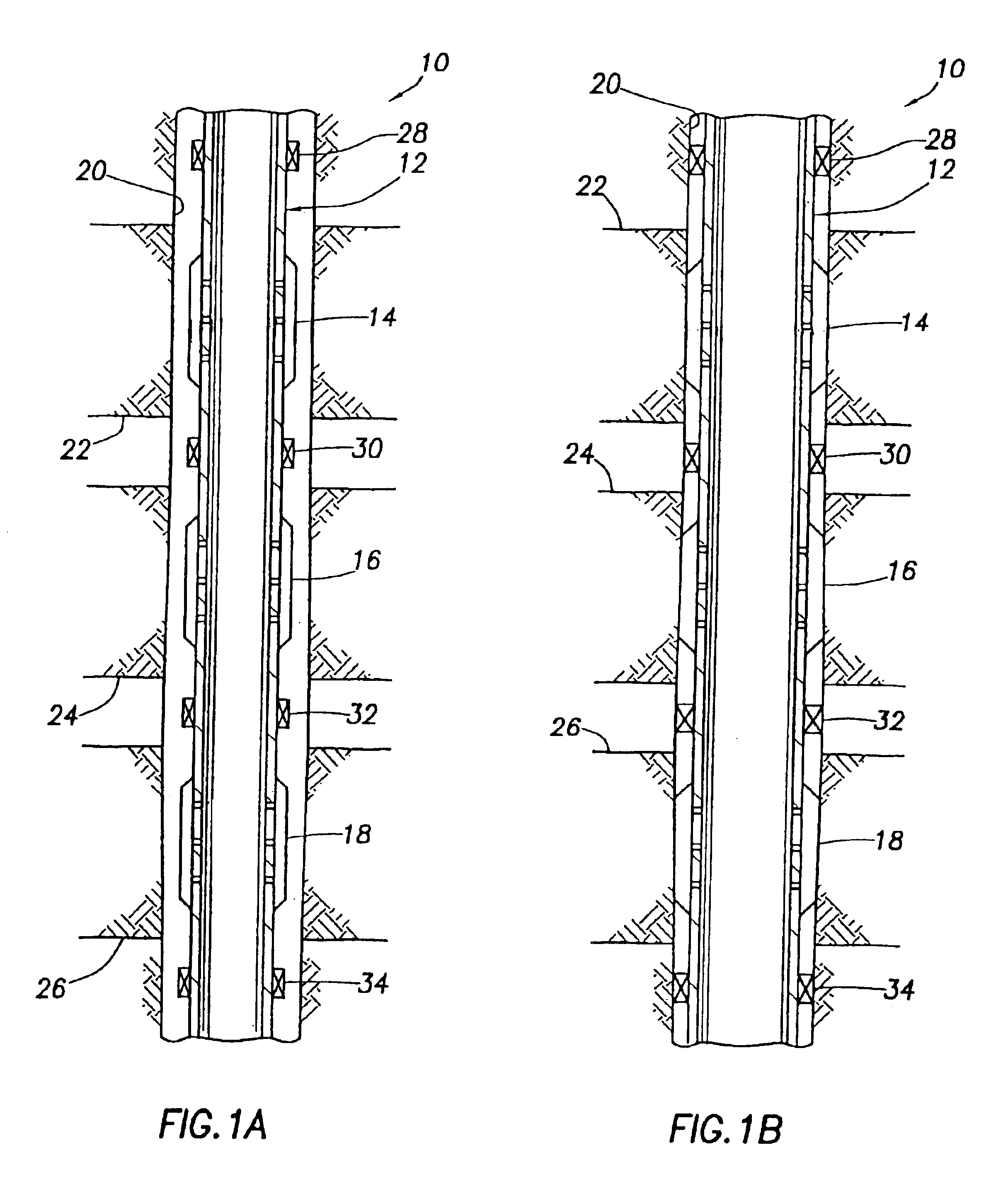
[0020]Representatively illustrated in FIGS. 1A and 1B is a method 10 which embodies principles of the present invention. In the following description of the method 10 and other apparatus and methods described herein, directional terms, such as “above”, “below”, “upper”, “lower”, etc., are used only for convenience in referring to the accompanying drawings. Additionally, it is to be understood that the apparatus representatively described herein may be utilized in various orientations, such as inclined, inverted, horizontal, vertical, etc., and in various configurations, without departing from principles of the present invention.

[0021]Referring initially to FIG. 1A, in the method 10, a screen assembly 12 including multiple expandable well screens 14, 16, 18 is conveyed into a wellbore 20. The wellbore 20 intersects multiple formations or zones 22, 24, 26 from which it is desired to produce fluids. The screens 14, 16, 18 are positioned opposite respective ones of the zones 22, 24, 26....


PUM

PropertyMeasurementUnit
Fractionaaaaaaaaaa
Fractionaaaaaaaaaa
Fractionaaaaaaaaaa

Abstract

An expandable well screen has a desirable thin-wall construction together with a simplified fabrication method. In fabricating the screen, a flexible sheet of metal mesh filter media is diffusion bonded to an inner side of a perforated metal sheet which is then deformed to a tubular shape to form a filter structure having an outer perforated tubular shroud interiorly lined with the filter media. The tubular filter structure is telescoped onto a perforated base pipe and has its opposite ends sealingly secured thereto to complete the expandable well screen.

Description

CROSS-REFERENCE TO RELATED APPLICATION[0001]This application is a continuation of U.S. application Ser. No. 10 / 109,154, filed on Mar. 28, 2002 now U.S. Pat. No. 6,619,401 and entitled “METHODS OF COMPLETING A SUBTERRANEAN WELL”, which was a division of U.S. application Ser. No. 09 / 574,658, filed on May 18, 2000 now U.S. Pat. No. 6,415,509 and entitled “METHODS OF FABRICATING A THIN-WALL EXPANDABLE WELL SCREEN ASSEMBLY” (As amended), such applications being hereby incorporated by reference herein in their entireties. Further, this application discloses subject matter similar to that disclosed in copending U.S. application Ser. No. 09 / 565,899 filed on May 5, 2000, entitled “EXPANDABLE WELL SCREEN”, and having Ana M. Castano-Mears, John C. Gano and Ralph H. Echols as inventors. Such copending is also hereby incorporated by reference herein in its entirety.BACKGROUND OF THE INVENTION[0002]The present invention generally relates to filtration apparatus and, in a preferred embodiment ther...

Claims


Application Information

Patent Timeline
IPC IPC(8): B01D29/15B01D29/13E21B43/10E21B43/08E21B43/02
CPCB01D29/15E21B43/084E21B43/086E21B43/103E21B43/108B01D29/58B01D2201/0407Y10T29/49904Y10T29/49604Y10T29/49602Y10T29/49908
Inventor ECHOLS, RALPH H.SIMONE, ANTHONY D.HOPKINS, SAM A.
Owner HALLIBURTON ENERGY SERVICES INC
Learn More