Baggage

Active Publication Date: 2005-09-13
VANGUARD CORP
View PDF19 Cites 23 Cited by
  • Summary
  • Abstract
  • Description
  • Claims
  • Application Information

AI Technical Summary

Benefits of technology

[0007]In view of the foregoing, it is an object of the invention to provide a baggage which can effectively prevent the theft without reducing usability while being able to be simply manufactured at low cost by workshop modification from the existing suitcase, and the grip device installed on the baggage main body.
[0011]When a wire storing portion is provided in the locking device to be able to wind and store the wire, a pullout length of the wire toward the outside of the baggage main body can be adjusted, and the usability can be further improved. The connection position of one end portion of the wire and the connection portion connecting the other end portion are arranged so as to be close to the locking device. Therefore, a size of the closed loop can be minimized and the overall length of the wire can be shortened, when the wire is winded around a structure such as the pillar.
[0012]With reference to the installation of the locking device in the baggage main body, for example, it is possible that the locking device is fitted in and fixed to the inside of the baggage main body having a proper thickness surrounding a hollow portion which becomes the baggage housing space. In this case, when the workshop modification of the existing baggage is performed, the manufacturing is easy to perform and manufacturing cost can be suppressed to a lower level. Further, because the both end portions of the wire are held by one point of the baggage main body to which the locking device is fixed, securing the strength does not reduce ease of carry.
[0014]A point where the locking device is installed in the baggage main body can be properly determined in consideration of weight balance of the baggage main body or the usability. In the case where the locking device is installed in a grip provided in the baggage main body, the locking device can be provided without reducing an appearance of the baggage while a part of the locking device is protruded from the baggage main body. Therefore, the locking device can be prevented from protruding to the inside of the baggage housing space of the baggage main body in the case where the locking device is larger than a thickness of the baggage main body, and locking and unlocking operability can be improved in the case where the locking device is formed by a dial type locking device. It is desirable that connection direction of the pulled-out wire and the locking device is set on the side of the baggage main body so that the wire is easily winded around the standing pillar or the like.
[0017]In the storage of the pulled-out length of the wire in the wire storing portion, storage efficiency can be improved by, for example, winding the wire about a winding member such as a shaft, and it is also possible to utilize a simple automatic winding device using a spiral spring. In this case, winding operation and pullout operation can become smooth to improve the usability by guiding the wire so that the wire substantially becomes a tangential line relative to a winding position, for example, a rotational locus of the winding member. The guide of the wire to the winding position can be performed by providing a guide opening at the corresponding position of a cover member covering the locking device, namely, by utilizing the fixing portion which fixes the grip to the baggage main body. In the case where a hand grip portion is rotatably connected to the cover member, it is possible to increase a degree of freedom of the arrangement of the components exposed to the outside of the cover member, which include a locking and unlocking operation portion and the connection portion which constrains the free end portion of the wire by the locking operation with the locking and unlocking operation portion in addition to the guide opening, and operability of the locking device can be also improved.

Problems solved by technology

The wire and the baggage main body are strongly connected to each other by integrating the locking device with the baggage main body, and the wire does not easily disengage the baggage even when the closed loop is forcedly hauled outside the baggage main body.

Method used


Image

  • Baggage
  • Baggage
  • Baggage

Examples


Embodiment Construction

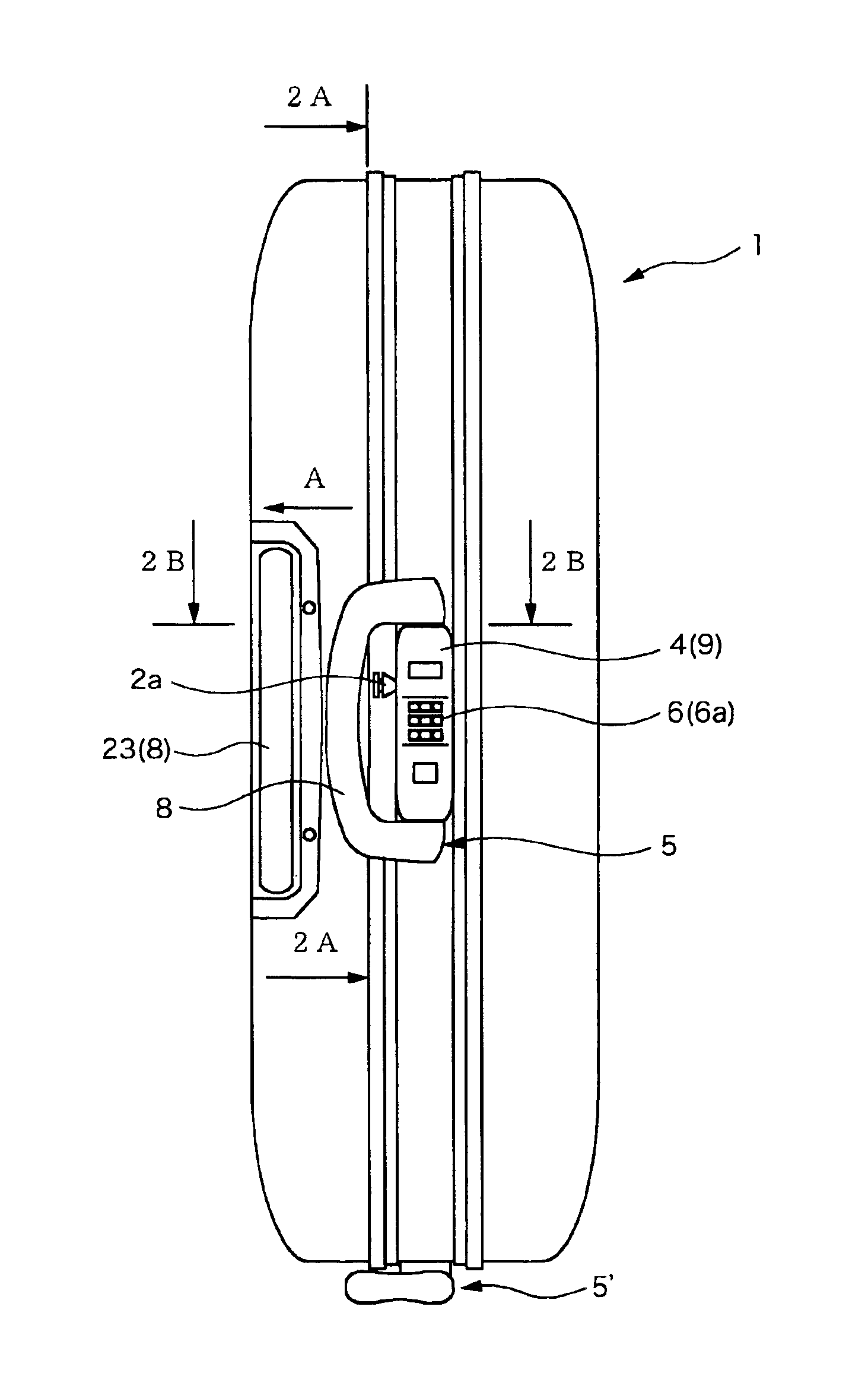
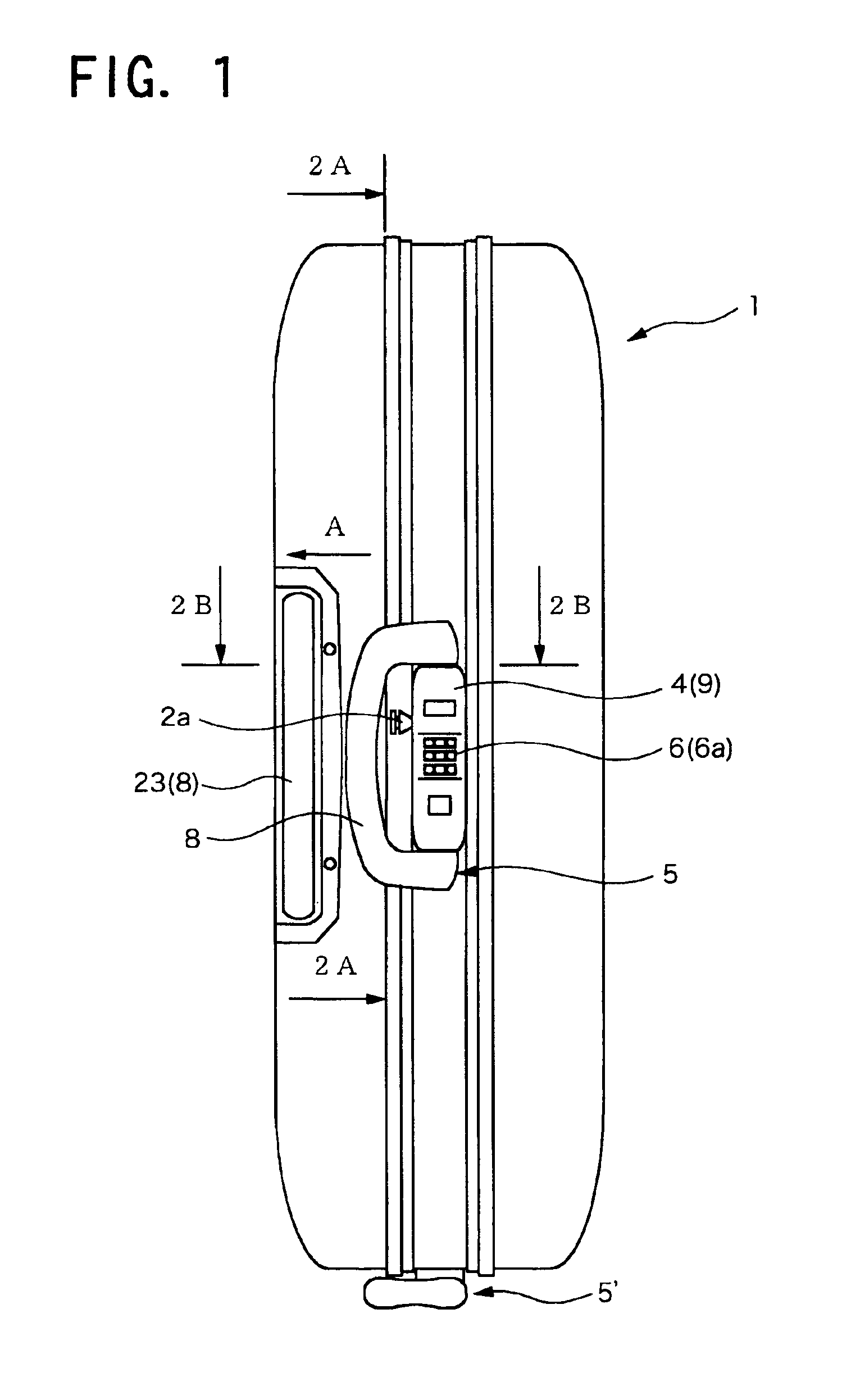
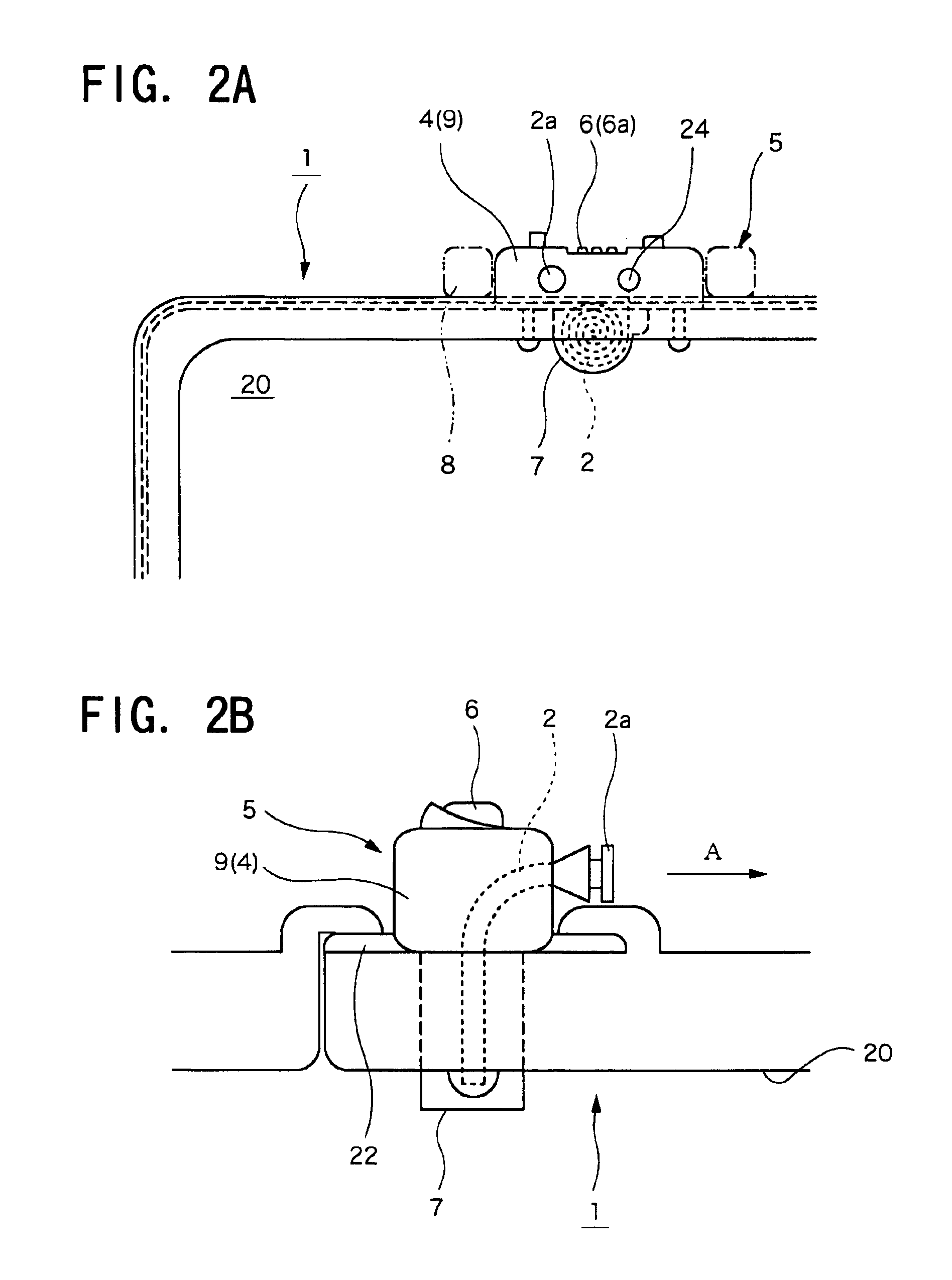
[0028]FIGS. 1 to 4 show an embodiment of the invention. In the embodiment, the baggage is the suitcase whose baggage main body 1 is made of ABS resin, and a plurality of wheels 21 is rotatably attached beneath the main body 1 in which a baggage housing space 20 is formed. In the baggage main body 1, the baggage housing space 20 can be opened by a hinge (not shown) provided in a lower portion, grips 5 and 5′ are included at two points of an upper surface and one side surface, and an attachment which can attach and remove the wheel (not shown) is formed on the other side surface opposite to one side surface of the baggage main body 1 where the grip 5′ is formed. Therefore, the suitcase can be easily carried without lifting the baggage main body 1 by the wheels 21 on the lower surface side when the suitcase is pulled by the grip 5 on the upper surface side, and by attaching the wheel to the attachment formed on the opposite side surface when the suitcase is pulled by the grip 5′ on one...


PUM


Abstract

A baggage, which can effectively prevent theft without damaging its utility and can simply be manufactured at low cost by workshop modification from existing baggage. The baggage has a locking device, which can constrain both end portions of a wire by locking operation to form a closed loop. The locking device is fixed to the baggage main body. The locking device can be subassembled in a grip attached to the baggage main body, and the baggage can be simply manufactured by replacing the subassembly with the grip of the existing suitcase.

Description

BACKGROUND OF THE INVENTION[0001]1. Field of the Invention[0002]The present invention relates to a baggage and a grip device installed on a baggage main body.[0003]2. Description of the Related Art[0004]A theft-prevention suitcase, which utilizes a rope as a theft-prevention belt by connecting a rope to a baggage while the rope can be locked and unlocked, is described in Japanese Patent Application Laid-Open No. 11-155623. In this conventional example, in the theft-prevention suitcase, a fit portion and a locking device which can connect an end portion of the rope are provided while exposed to the outside, and a closed loop is formed outside the suitcase by fitting one end of the rope into the fit portion while the other end engages the locking device.[0005]However, the conventional example has a drawback that production takes many man-hours and production cost is also expensive because the fit portion and the locking device are individually formed in the suitcase.[0006]It is necess...

Claims


Application Information

Patent Timeline
IPC IPC(8): E05B67/00E05B37/02E05B65/52E05B37/00E05B73/00E05B65/00A45C13/20A45C13/28
CPCA45C13/20A45C13/28E05B73/0011E05B37/02E05B65/52Y10T70/409Y10T70/435Y10T70/5757Y10T70/5062Y10T70/5058
Inventor IWAMOTO, SHINGO
Owner VANGUARD CORP
Why Eureka
Try Eureka