Self-adjusting locking pliers

a technology of locking pliers and self-adjusting, which is applied in the field of pliers, can solve the problems of not being able to design practical and truly functional pliers

Inactive Publication Date: 2005-09-13
HILE JEFFREY B
View PDF6 Cites 36 Cited by
  • Summary
  • Abstract
  • Description
  • Claims
  • Application Information

AI Technical Summary

Benefits of technology

[0005]The self-adjusting locking pliers of the present invention include a stationary assembly having an elongated overall shape wherein one end of this stationary assembly forms a stationary handle and the other end of the stationary assembly forms a stationary jaw, and a moveable assembly including an operating lever and a moveable jaw that is supported on the stationary jaw via a first pivot which is comprised of a slidable pivot connection whereby the moveable jaw is permitted to close down on an object disposed between the jaws for providing self-adjustment of the jaws for different sized objects to be gripped between the jaws. The front end of the operating lever is supported on the stationary jaw via a second pivot which is comprised of a slidable pivot connection and the rear end of this operating lever forms a moveable handle. A spring biases the moveable handle away from the stationary handle.
[0007]A protrusion is also provided on the front end of the second link which is dimensioned for retaining an end of the spring at a position that is located in front of the fifth pivot when the pliers are open and in rear of the fifth pivot when the pliers are closed. A stop mechanism is also provided for preventing the toggle mechanism from going beyond a point of alignment past dead center in either direction upon movement of the moveable handle toward and away from the stationary handle. This combination of elements provides a plier which is both self-adjusting and locking and which may be easily operated without having to learn special operating procedures.

Problems solved by technology

However, in spite of continuous efforts in this field, no one has been able to design practical and truly functional pliers which are both self-adjusting and locking.

Method used


Image

  • Self-adjusting locking pliers
  • Self-adjusting locking pliers
  • Self-adjusting locking pliers

Examples


Embodiment Construction

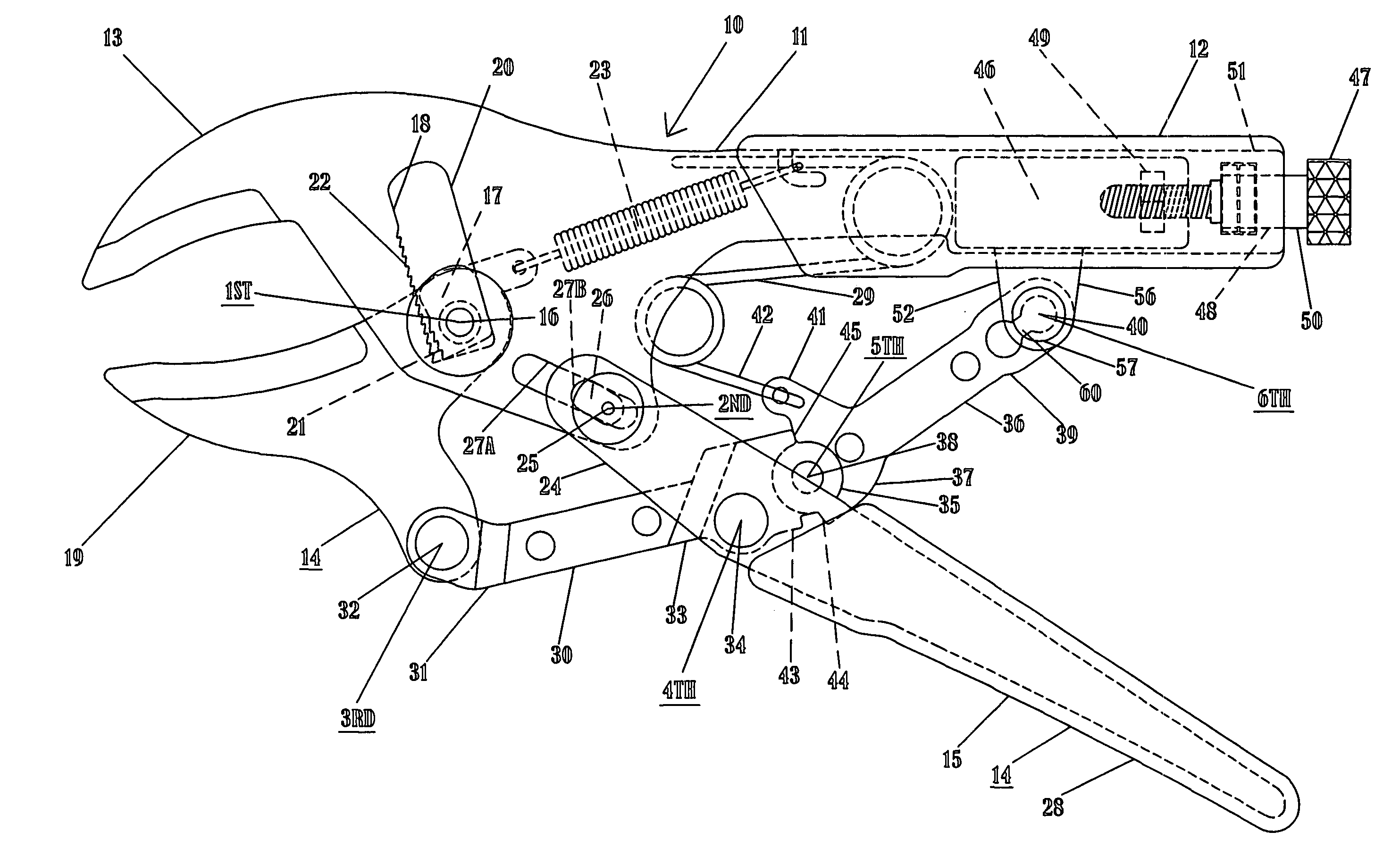
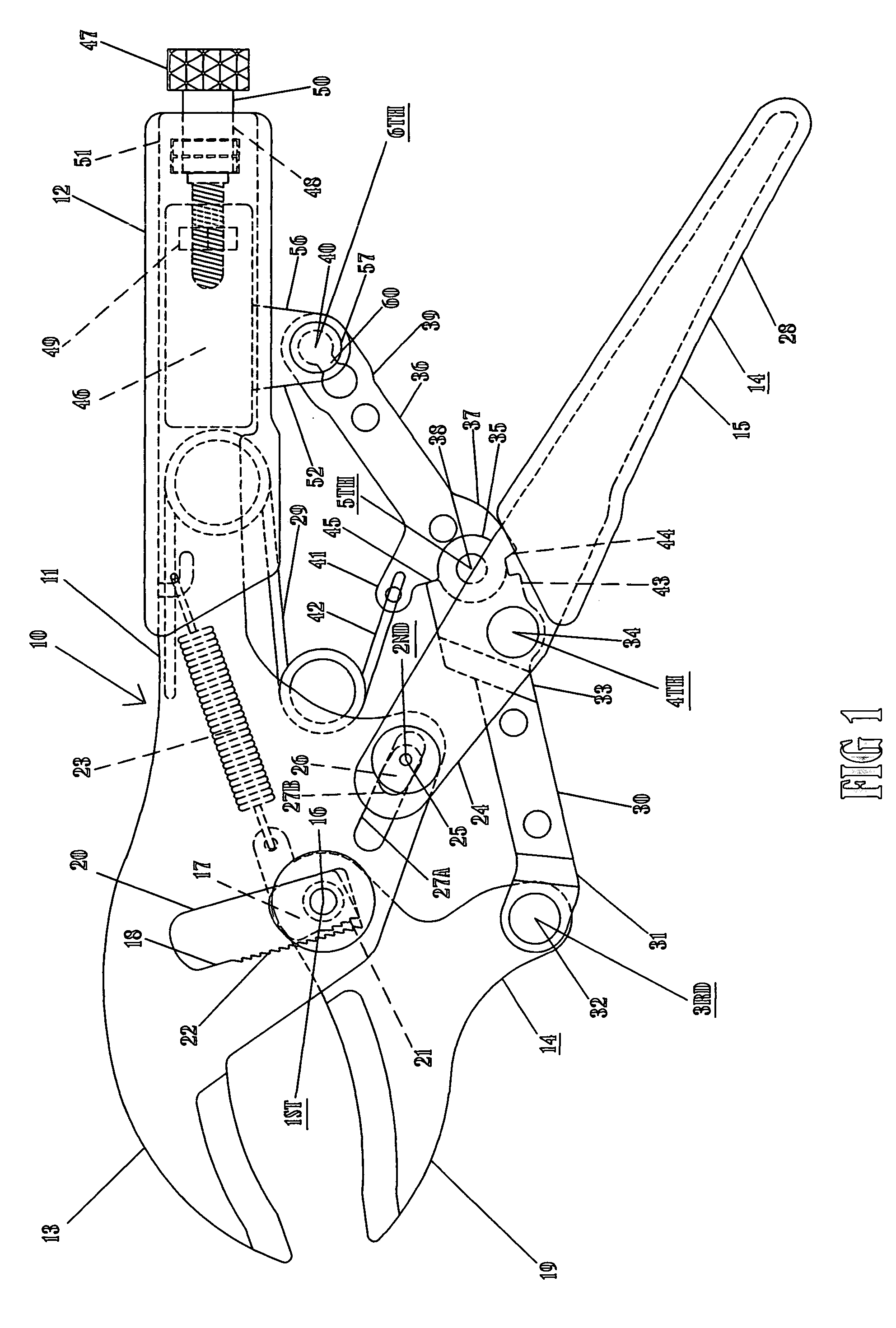
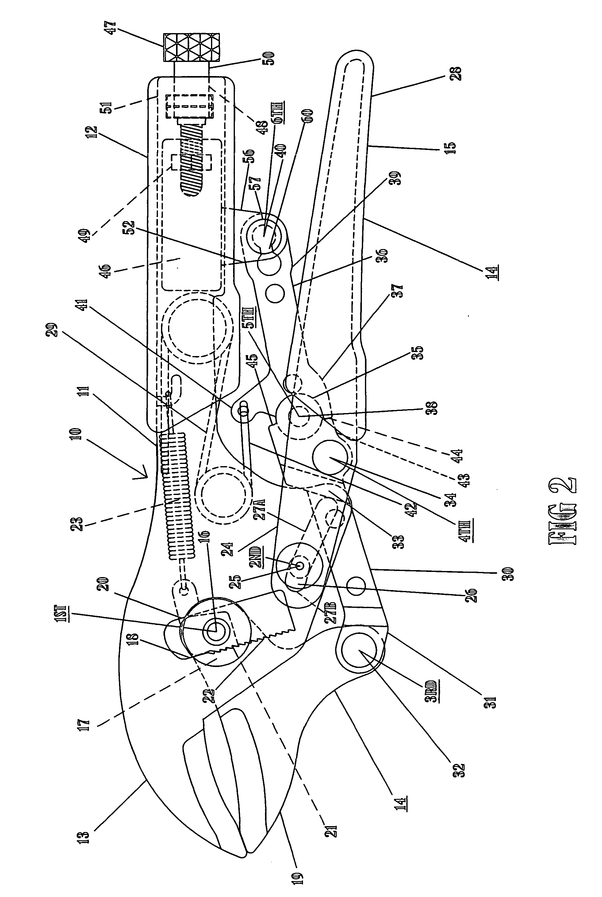
[0021]Referring to the drawings, the self-adjusting locking pliers 10 of the present invention is comprised of a stationary assembly 11 having an elongated overall shape wherein the rear end 12 of the stationary assembly 11 forms a stationary handle, and the other or forward end 13 forms a stationary jaw. A moveable assembly 14 includes operating lever 15 that is supported on stationary jaw 13 via first pivot 16 which is comprised of a slidable pivot connection that includes spring biased pawl 17 and ratchet 18. Pawl 17 is secured to moveable jaw 19 by first pivot 16 and the pawl 17 is moveable within slot 20 that extends in stationary jaw 13 generally transversely to the jaws 13 and 19. Pawl 17 is provided with forwardly facing teeth 21 for engaging the rack of teeth 22 which provides ratchet 18 on the front edge of slot 20. Spring 23 is connected between pawl 17 and stationary assembly 11 for maintaining pawl teeth 21 normally disengaged from rack teeth 22.

[0022]Since the pliers b...


PUM


Abstract

A self-adjusting locking plier having a stationary assembly providing a stationary handle and a stationary jaw and a moveable assembly including an operating lever and a moveable jaw that is supported on the stationary jaw with a slidable pivot connection whereby the moveable jaw is permitted to automatically close down on an object disposed between the jaws for providing self-adjustment for different sized objects to be gripped between the jaws. The operating lever is spring biased to move away from the stationary handle. In addition, a dual link past-dead-center toggle locking mechanism is provided to lock the pliers on to an object gripped between the jaws. The specific arrangement of the locking toggle mechanism in combination with the moveable operating lever to which it is connected in further combination with the fact that the front end of the lever mechanism is connected with a slidable pivot to the stationary jaw provides a self-adjusting locking plier.

Description

BACKGROUND OF THE INVENTION[0001]This invention relates to pliers, and more particularly, to self-adjusting pliers which also lock with a strong clamping force on an object.[0002]Self-adjusting or auto-adjusting pliers are commonly found on the market. Such pliers have jaws which are self-adjusting accordingly to the size of the work piece to be grasped between the jaws. Examples of such self-adjusting pliers are disclosed in U.S. Pat. Nos. 6,065,376 and 6,279,431.[0003]Also commonly found on the market are locking pliers which incorporate a compound toggle locking mechanism or linkage whereby when the moveable jaw of the plier is adjusted to seize a work piece firmly between the moveable and the fixed jaw and the handles are tightly compressed, the toggle mechanism locks the hand tool onto the work piece. Examples of this type of plier are disclosed in U.S. Pat. No. 5,056,385 (a locking plier sold under the trademark VISE-GRIP) and U.S. Pat. No. 6,227,080.[0004]However, in spite of...

Claims


Application Information

Patent Timeline
Patent Type & Authority Patents(United States)
IPC IPC(8): B25B7/12B25B7/10B25B7/00
CPCB25B7/10B25B7/123
Inventor HILE, JEFFREY B.
Owner HILE JEFFREY B
Why Eureka
Try Eureka