Tubing expansion

a technology of expansion and tubing, which is applied in the direction of sealing/packing, mechanical equipment, and borehole/well accessories, etc., can solve the problems of unfavorable loss of liner internal diameter, and achieve the effect of reducing the modulus of elasticity and great yield strength

Inactive Publication Date: 2005-09-13
WEATHERFORD TECH HLDG LLC
View PDF12 Cites 20 Cited by
  • Summary
  • Abstract
  • Description
  • Claims
  • Application Information

AI Technical Summary

Benefits of technology

[0019]In both aspects of the present invention, selection of the properties of the tubulars facilitates provision of interference between the tubulars; the elastic recovery of the outer second tubular will be greater than the elastic recovery of the inner tubular. Earlier proposals have suggested that this effect may be achieved using tubulars formed of similar materials. However, where similar materials are utilised, this effect is less easily achieved, and in some cases may result in minimal or even no coupling between the tubulars. It is believed that this problem may have been disguised in prior proposals by the provision of elastomeric seals and the like between the tubulars; the poor coupling between the tubulars themselves may not have been apparent due to the coupling effect provided by the expanded seals.

Problems solved by technology

There is an undesirable loss of liner internal diameter associated with the provision of conventional liner hangers, and this is one reason behind the development of alternative hanger arrangements, such as proposed in WO99\18328 (Bailey et al).

Method used


Image

  • Tubing expansion
  • Tubing expansion
  • Tubing expansion

Examples


example 2

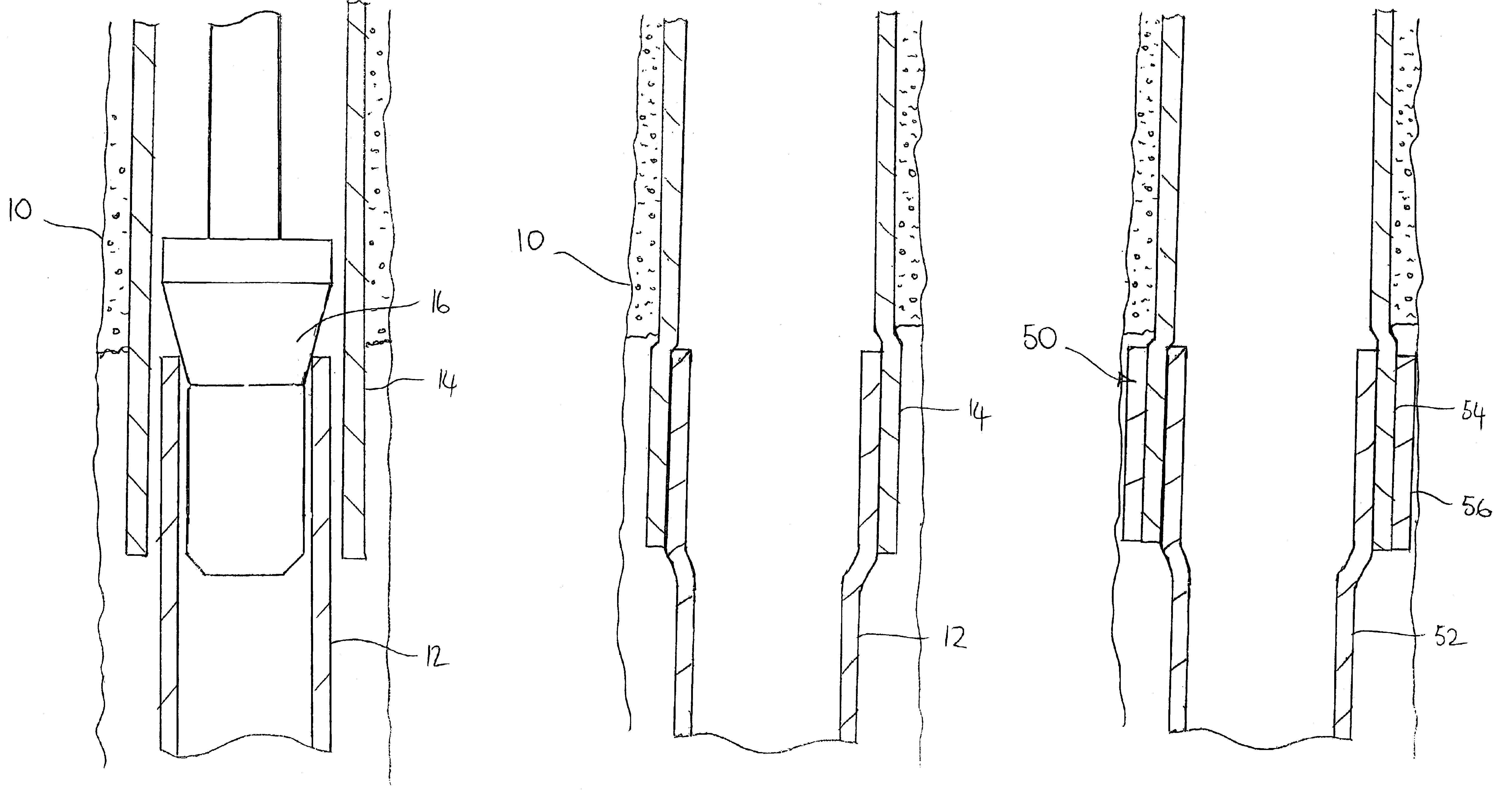
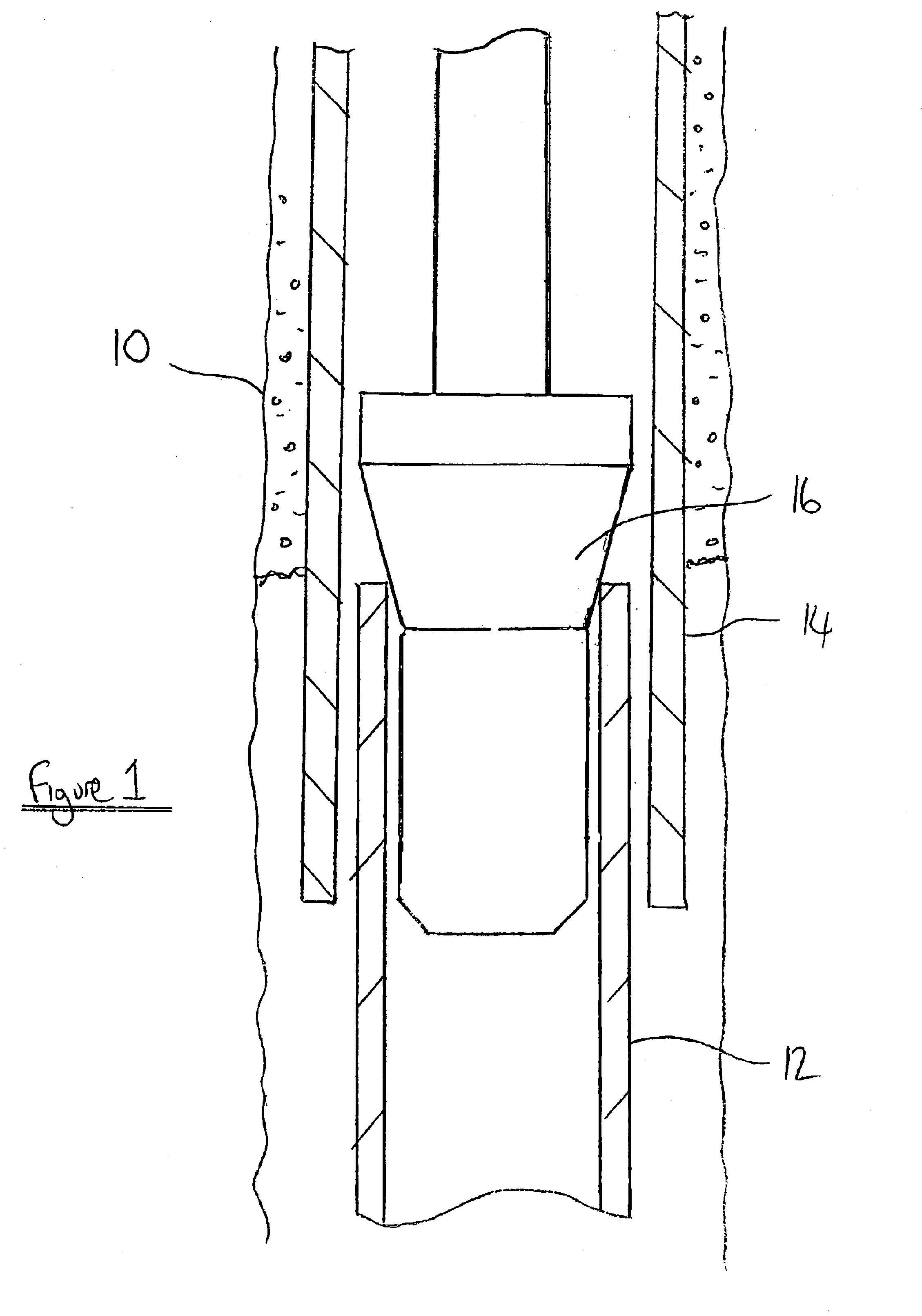
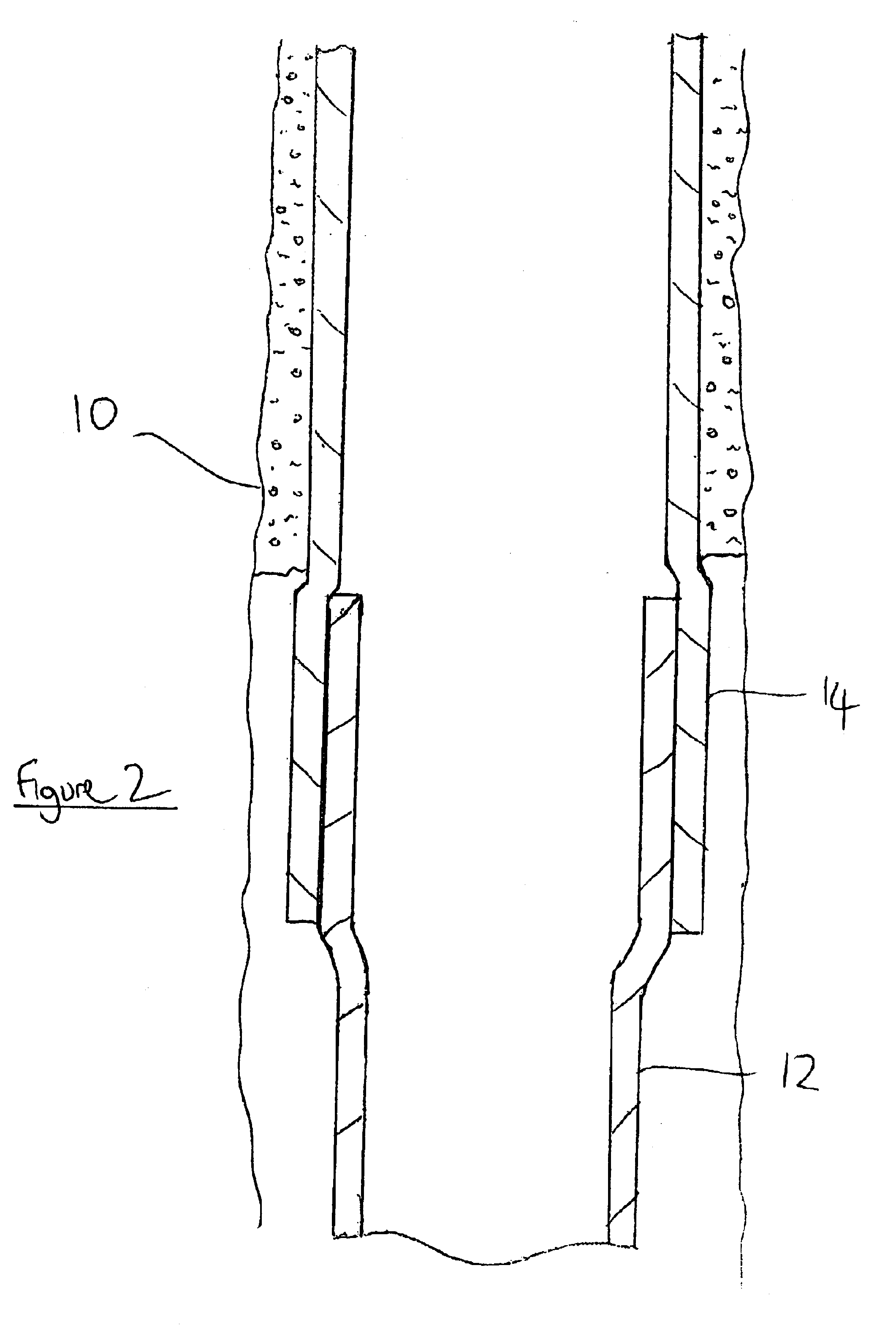
[0039]In a second example, the liner 12 is in the form of A106 Grade B line pipe with a yield strength of 46,500 psi, while the casing 14 is in the form of L80 casing with a yield strength of 98,500 psi. The initial outside diameter of the liner 12 and the inside diameter of the casing 14 are both approximately 7 ⅝″, and both have a wall thickness of 3 / 8″.

[0040]The degree of expansion was selected such that both the liner 12 and casing 14 experienced stress 10% above their yield positions.

[0041]Once the expansion force is removed, and the tubulars 12, 14 are permitted to relax, a contact stress of 2400-2500 psi (determined by FEA) is created between the tubulars due to the differential elastic recovery of the liner 12 and casing 14. This level of stress is sufficient to permit the liner to be hung from the casing 14 and, assuming the contacting surfaces are reasonably smooth, creates a fluid-tight seal between the tubulars, obviating the requirement for elastomeric seals.


PUM


Abstract

A method of coupling first and second tubulars (12,14) comprises providing a first tubular having a first yield strength and a second tubular having a higher second yield strength. A portion of the first tubular is located within and overlapping a portion of the second tubular and the first tubular is expanded sufficient to expand the second tubular, at least the first tubular being expanded beyond its yield point. Following expansion, a degree of elastic contraction of the tubulars is permitted, sufficient to provide interference between the tubulars.

Description

FIELD OF THE INVENTION[0001]The present invention relates to tubing expansion. In particular, the invention relates to expansion of a first tubular within a larger diameter second tubular to provide interference between the tubulars.BACKGROUND OF THE INVENTION[0002]In the oil and gas exploration and extraction industry, well bores are lined with metal tubing. Typically, the majority of a well will be lined with tubing known as casing, while the distal end of the well is provided with smaller diameter tubing known as liner. Generally, the section of the well provided with the liner will intersect the hydrocarbon-bearing formation. The liner may be suspended from the lower end of the casing by means of a liner hanger.[0003]Conventionally, the liner hanger is a tubular assembly which is mounted on the upper end of the liner. The hanger is run into the casing with the liner and then configured first to engage and then to seal with the casing inner surface.[0004]There is an undesirable l...

Claims


Application Information

Patent Timeline
Patent Type & Authority Patents(United States)
IPC IPC(8): E21B43/10E21B43/02
CPCE21B43/103E21B43/106E21B43/10E21B43/105F16L13/16
Inventor SIMPSON, NEIL ANDREW ABERCROMBIE
Owner WEATHERFORD TECH HLDG LLC
Why Eureka
Try Eureka