Cap for container

a container and cap technology, applied in the field of caps, can solve the problems of difficult to obtain a high quality design of the container using such a cap, and achieve the effect of easy downward bending

Inactive Publication Date: 2005-09-13
NIFCO INC
View PDF15 Cites 15 Cited by
  • Summary
  • Abstract
  • Description
  • Claims
  • Application Information

AI Technical Summary

Benefits of technology

[0012]In the first aspect of the invention, one of the cap main portion and the ring member is molded with the injection molding before molding the other, so that the outer surface of the ring member is closely attached to the inner surface of the cap main portion on the cylindrical lower end side to thereby detachably integrate the ring member with the cap main portion. The cap having a partial separation function can be easily and adequately produced. At the same time, the cap member can not be removed from the upper portion of the container unless such a large twisting force as to separate both members is applied to the cap member. Thus, the cap member is not easily removed from the upper portion of the container, thereby eliminating a chance that the container is opened inadvertently.
[0013]In the first aspect of the invention, since the cap main portion is integrated with the ring member, the cap main portion can be separated from the upper portion of the container, i.e. the container can be opened, for the first time without applying an excessively large twisting force to the cap main portion. Also, the ring member is disposed inside the cap main portion before it is separated from the cap main portion, so that the upper portion of the container has a good appearance.
[0020]In the second aspect of the invention, it is possible to prevent the cap main portion from being integrated with the ring member inadvertently to an original state when the cap main portion is screwed in the container upper portion from the separated state of the cap main portion and the ring member.
[0022]Further, the forward ends of the engaging pieces are structured to hook on the extraction controlling projection from below due to the elasticity when the cap main portion is completely screwed in the upper portion of the container.
[0026]More specifically, after the cap main portion is removed from the container upper portion, when the ring member is pulled so that the container upper portion is extracted from the ring member, the ring member can be deformed so that the ring lower end side of the ring constituting members is outwardly expanded around the thin portion. When the ring member is deformed as described above, an angle between the cylinder axis of the cap main portion and a projecting direction of the engaging piece, which is formed on the inner periphery of the ring member and projected toward the cylinder upper end side of the cap main portion so that the forward end of the engaging piece can be hooked on the extraction controlling projection from the lower side, becomes slightly larger.
[0027]Accordingly, the engaging piece projecting upward pushes the extraction controlling projection and is easily bent downward. From this state, the ring member is pulled upward and extracted toward the lower side of the forward end of the engaging piece to move over the extraction controlling projection smoothly. Thus, the ring member on the container upper portion side is relatively easily removed from the container upper portion when the container is thrown away.

Problems solved by technology

However, the cap in the unopened state of the container does not provide a good appearance, thereby making it difficult to obtain a high quality design of the container using such a cap.

Method used


Image

  • Cap for container
  • Cap for container
  • Cap for container

Examples


Embodiment Construction

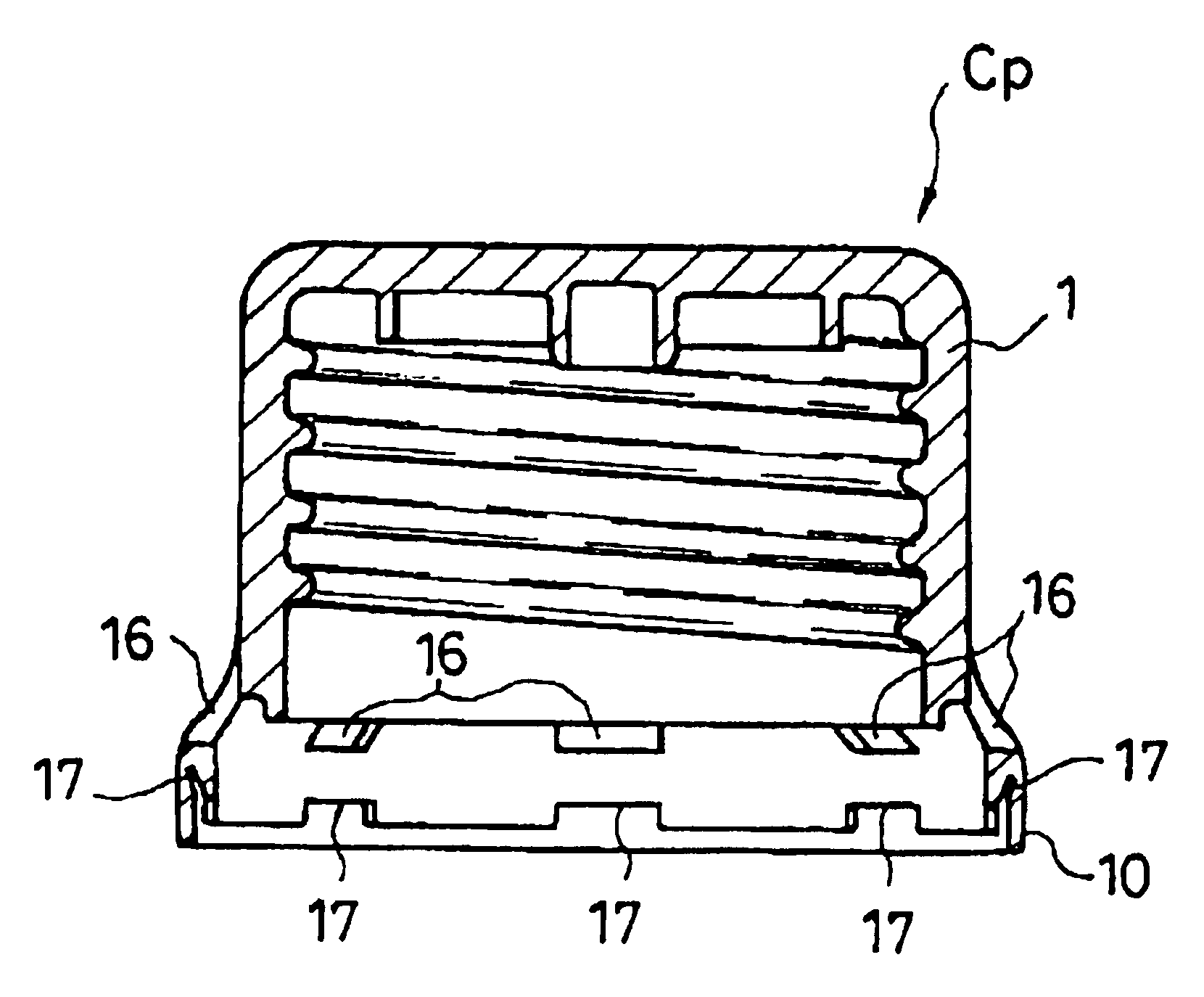
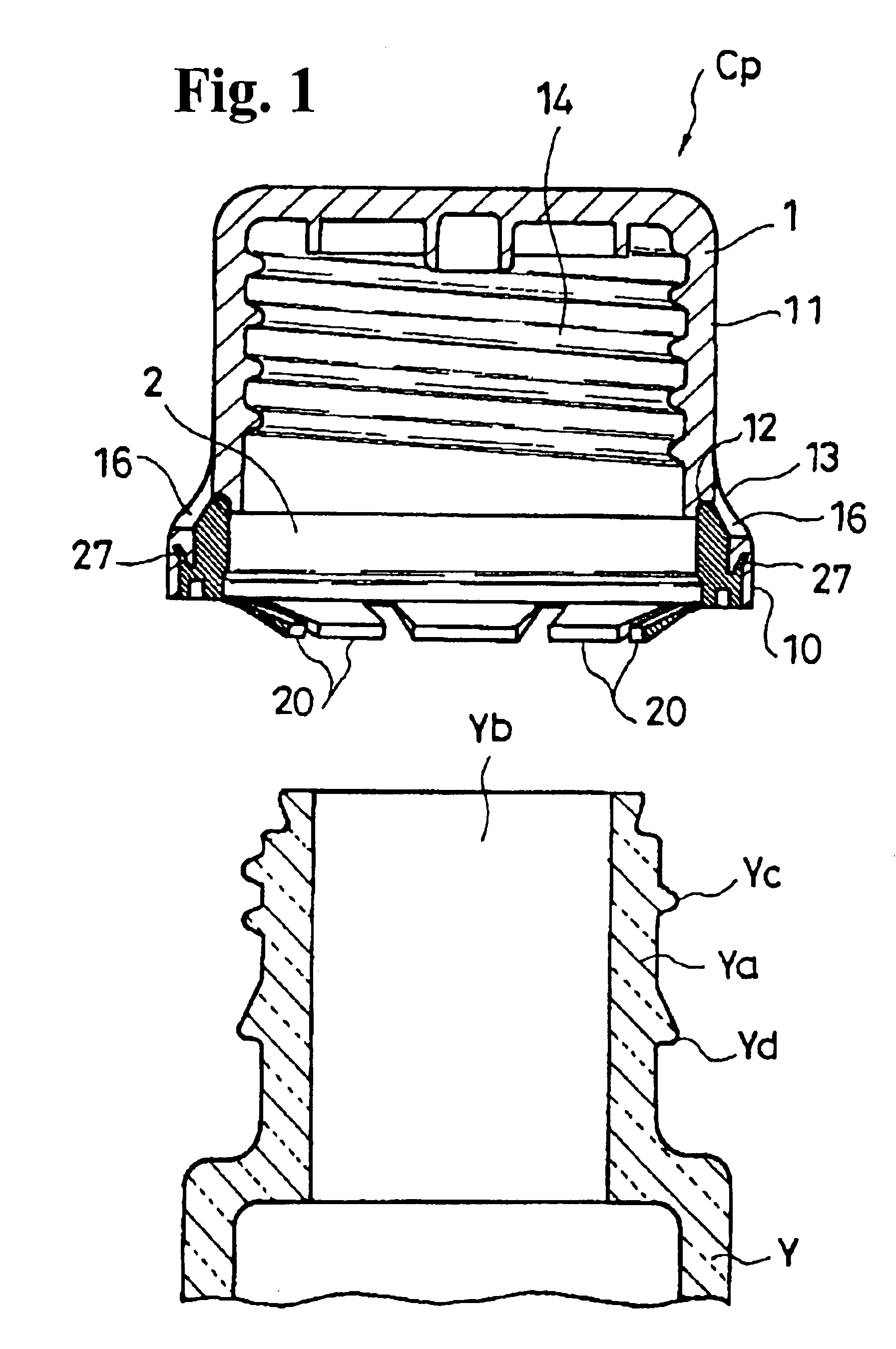
[0039]Hereunder, with reference to FIGS. 1 through 11, an embodiment of the present invention will be described in detail.

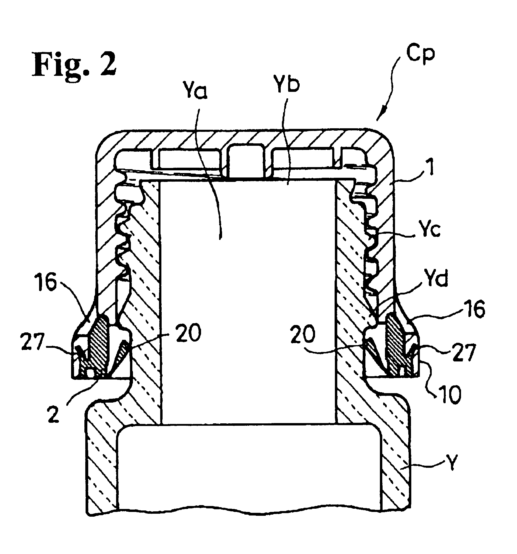
[0040]FIG. 1 shows a state right before a cap Cp according to the embodiment is attached to an upper portion Ya of a container Y; FIG. 2 shows a state that the cap Cp is attached to the container Y to seal the same; and FIG. 3 shows a state that the cap Cp is removed from the container Y to release the sealing of the container Y.

[0041]FIGS. 4 through 8 show the cap Cp; and FIGS. 9 through 11 show only a ring member 2 constituting a cap main portion 1 and the cap Cp and detachably integrated with the main portion of the cap Cp.

[0042]According to the embodiment, the cap Cp is screwed into an upper portion Ya of the container Y to seal an opening Yb of the upper portion Ya. A part of the cap Cp is separated when the cap Cp is removed from the container for the first time. Accordingly, the cap Cp has a function of indicating that the container Y has already been open...


PUM


Abstract

A cap is used for a container as a bottle or jar. The cap includes a cylindrical cap main portion with a closed upper end and an open lower end, and a ring member. The cap main portion is screwed in an upper portion of the cylindrical container to close an opening of the container with the closed upper end. The ring member includes engaging pieces formed on an inner periphery of the ring for hooking from below on an extraction controlling projection formed on an outer periphery of a base portion of the container. A plurality of window holes is disposed on a lower side of the cap main portion along a periphery thereof so that the integrated ring member can be seen from the outside.

Description

BACKGROUND OF THE INVENTION AND RELATED ART STATEMENT[0001]The invention relates to a cap for a container. The cap is screwed in an upper portion of the container to close an opening of the container. When the cap is removed from the container for the first time, a part of the cap is separated and remains on the container. Therefore, the cap has a function of indicating the container has already been opened.[0002]A cap for a container has been disclosed in Japanese Patent No. 2561260. The cap is screwed into an upper portion of the container to close an opening of the container. When the screwed cap is removed from the container, a part of the cap is separated so that it is recognized that the cap has already been opened.[0003]The cap disclosed in Japanese Patent No. 2561260 is formed of a cap main portion and a ring member. The ring member includes an engaging projection to be engaged with a step portion formed on a lower end of an outer peripheral surface of the cap main portion, ...

Claims


Application Information

Patent Timeline
Patent Type & Authority Patents(United States)
IPC IPC(8): B65D41/34
CPCB65D41/3438Y10S215/901B65D41/34
Inventor NISHIDA, RYUHEI
Owner NIFCO INC
Why Eureka
Try Eureka