Apparatus and Method For Measurement of the Film Cooling Effect Produced By Air Cooled Gas Turbine Components

a gas turbine and film cooling technology, applied in the direction of material heat development, optical radiation measurement, instruments, etc., can solve the problems of reducing the thermal efficiency of the engine, and reducing the life of the blade, so as to reduce the manufacturing cost and cycle time, improve the quality of the gas turbine components, and reduce the

Inactive Publication Date: 2011-05-19
MEYER TOOL
View PDF11 Cites 30 Cited by
  • Summary
  • Abstract
  • Description
  • Claims
  • Application Information

AI Technical Summary

Benefits of technology

[0017]The exemplary embodiment of the relative individual cooling effect data acquisition method, an infrared camera is first positioned to view a collection of cooling features. Once in position a controlled heat flux is applied to the outer surface of the airfoil. After a predetermined time, a controlled chilled gas pressure, coolant, is rapidly injected into the blade and discharged out a plurality of cooling features onto the outer surface of the airfoil. When the coolant is discharged onto the blade's hotter outer surface it generates an isolated film cooling effect to radiate near the cooling feature. Improperly formed features either have no cooling effect, or a significantly reduced effect. Throughout this data acquisition process the camera is operated to capture a series of infrared image frames at a named sample rate.
[0018]The exemplary embodiment of the relative individual cooling effect identification method begins with first acquiring the frame just prior to the release of the coolant (45) and next, the frame just prior to when the coolant flow is stopped. The difference between these two frames produces what is named the raw image. Within the raw image, a sub-array is defined. This sub-array defines the boundaries of pixels around where a group of cooling effects is expected to be. A pixel is a single temperature element in the raw image. Using a novel adaptive process, the sub-array is analyzed to identify film cooling effects within this array.
[0019]In the exemplary embodiment of the relative individual cooling effect classification method, if an individual cooling effect area is less than a statistically computed partial limit, the cooling effect area is set to equal zero and the effect is classified as missing. If the cooling effect area is greater than a statistically computed blob limit, the cooling effect area is set to equal zero and its effect is classified as missing. If no cooling effect is identified where a cooling effect is expected, then the individual cooling effect area is set to zero and its effect is classified as missing. Otherwise, the individual cooling effect is classified as thru and its area set to the pixel count of the identified effect.
[0020]In the exemplary embodiment of the absolute individual film cooling effect quantification method, the total cooling effect area is computed as the sum of the relative individual cooling effect areas. Then the proportion of an individual cooling effect area relative to the total cooling effect area is computed. Finally the measure of each film cooling effect is quantified as the product of its proportion of total cooling effect area, the corrected mass rate of airflow and a correction factor to compensate for differences in test conditions used to generate the infrared signature of the relative individual film cooling effect.
[0021]With the film cooling effect quantified, its measurement is then compared with the limit for the design intent. If the design intent is unknown, then a sample of known good quality blades is inspected using this invention and statistical limits computed for use in determining the degree of film cooling effect conformance.
[0022]These and other objects and advantages of the present invention will become more readily apparent during the following detailed description taken in conjunction with the drawings herein. This invention significantly improves the quality of gas turbine components at a reduced manufacturing cost and cycle time.

Problems solved by technology

The coolant used for this purpose is extracted from the compressor, resulting in a reduction in the thermal efficiency for the engine.
Furthermore, if the film cooling effect is severely out of location, the blade's life span will be decreased.
As in the case of an aircraft engine, this decreased lifespan could result in the loss of life.
Research and development methods are distinguished by their enormous instrumentation, operational costs and considerable amount of time needed to accomplish a measurement.
Manufacturing methods are characterized as being cheaper and quicker, but do not directly measure the film cooling effect and rarely measure every individual film cooling feature which would require isolation from the remaining plurality of features.
The cost and time associated with using these methods prohibit their use in a manufacturing environment.
All of these manufacturing methods are repetitive, time-consuming and rely on human intervention.

Method used


Image

  • Apparatus and Method For Measurement of the Film Cooling Effect Produced By Air Cooled Gas Turbine Components
  • Apparatus and Method For Measurement of the Film Cooling Effect Produced By Air Cooled Gas Turbine Components
  • Apparatus and Method For Measurement of the Film Cooling Effect Produced By Air Cooled Gas Turbine Components

Examples


first embodiment

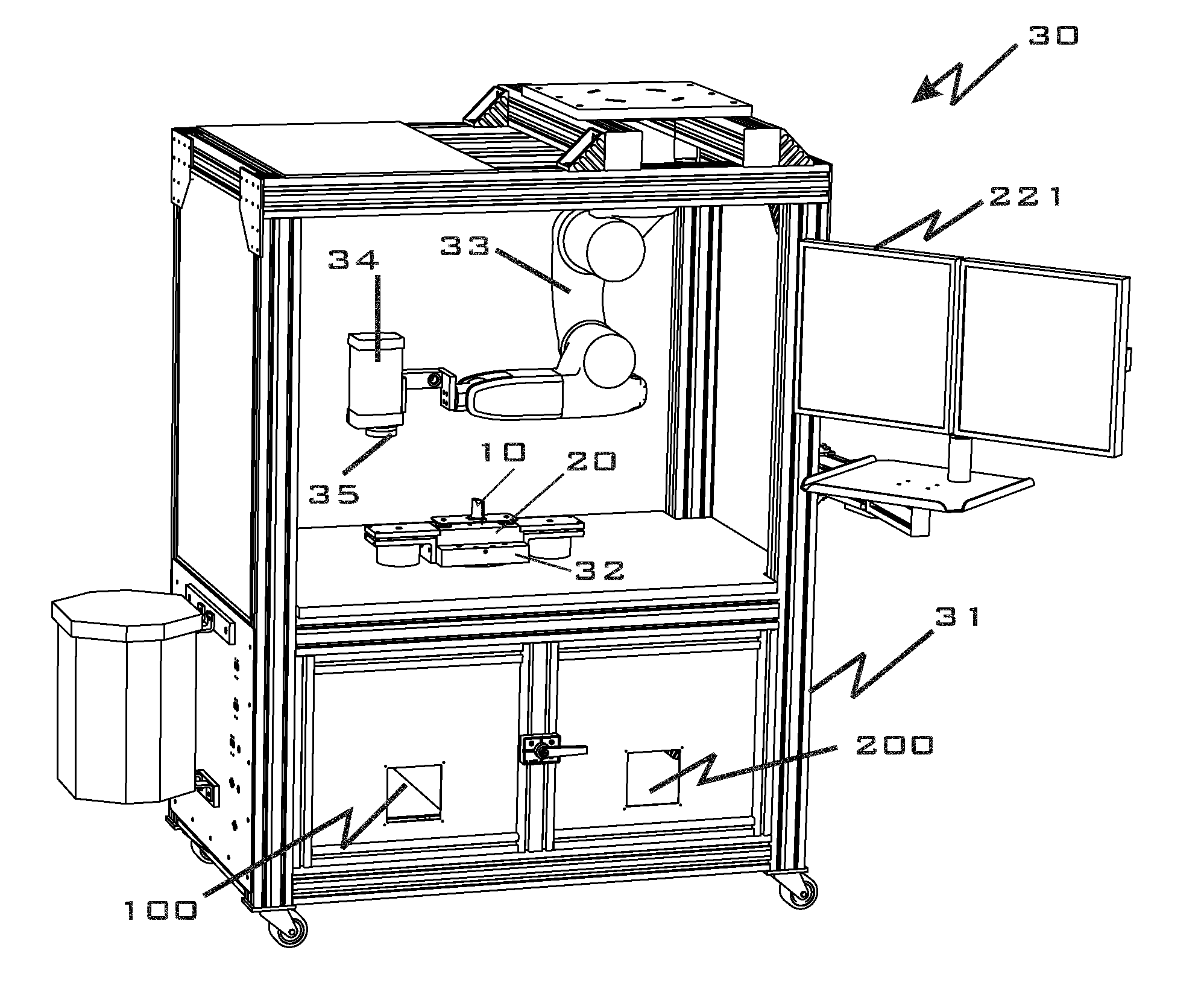
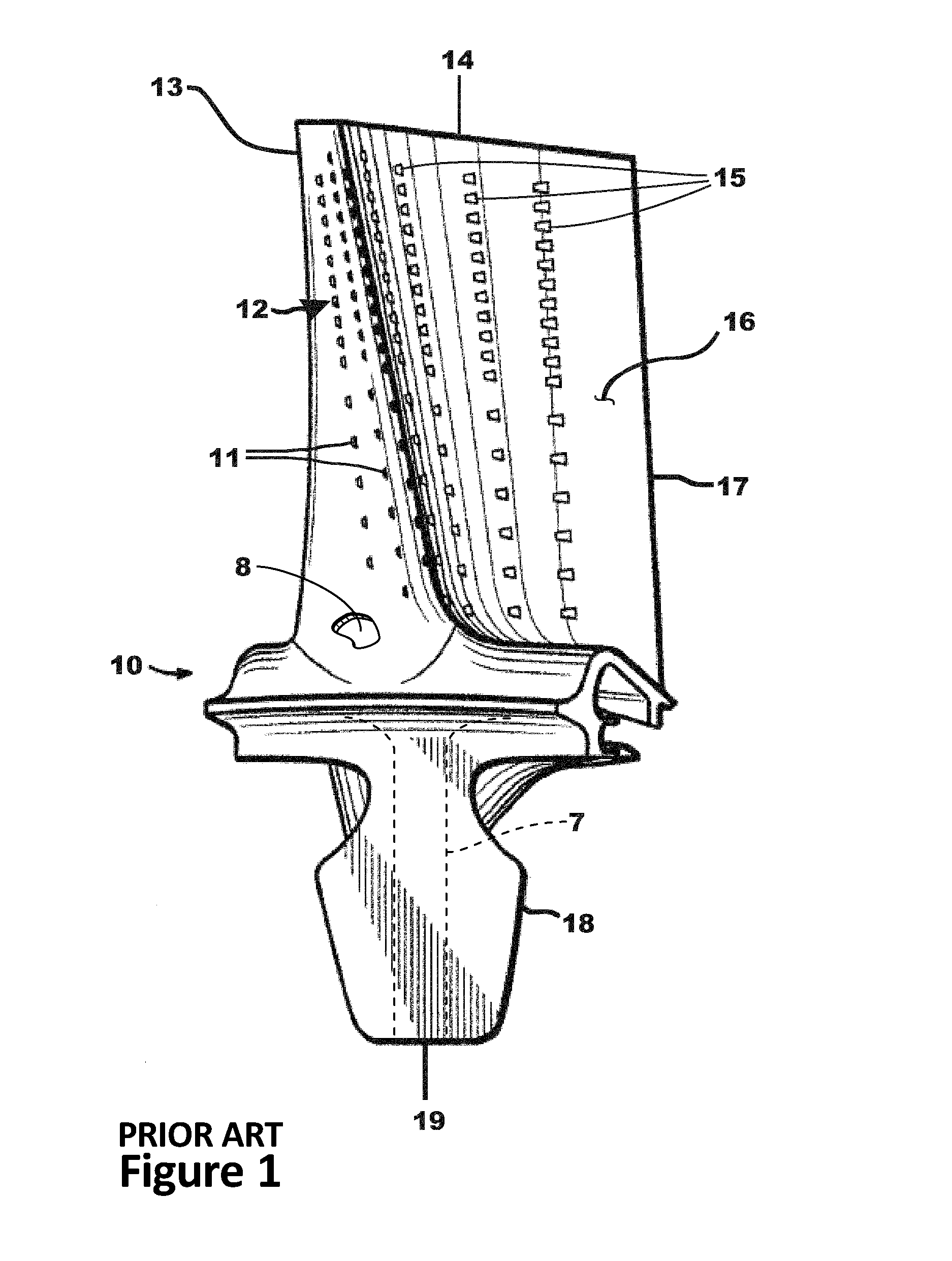
[0055]Referring to FIGS. 1, 3, 4, 5, 7, 7A and 7B, an apparatus (30), the coordinated assemblage of both an airflow test machine (30a) and an infrared inspection machine (30b) is housed in the same cabinet (31). This apparatus (30), named a “film cooling inspection machine” is used to measure the film cooling effect (40) generated by film cooling features or openings (12) fabricated in a known blade (10). Common to both the airflow test machine (30a) and an infrared inspection machine (30b) is a flow fixture (20) for holding the blade (10) and a diverter valve (62) that isolates the two machines.

[0056]Referring to FIGS. 1, 4, 5, 6, 7 and 9, the blade (10) to be inspected is supported in the blade adapter plate (25), as best shown in FIG. 5. This adapter plate (25) is held in place on top of the flow fixture (20) which is mounted on top of the plenum fixture (32) which in turn is mounted in the middle of the cabinet (31) of the film cooling inspection machine (30), as shown in FIG. 4...

second embodiment

[0062]Referring to FIGS. 7A and 7B and equations 12, 13 and 26, in the apparatus, the airflow test and infrared inspection machines (30a, 30b) are discrete machines. In this embodiment, once both the mass rate of airflow, ms or mc, and relative individual cooling effect, Ai, have been measured, the absolute individual film cooling effect Ei, is determined by the method described herein, except the mass rate of airflow and relative individual cooling effect area are recalled from the network database (300), prior to executing the herein described quantification process. This quantification process is coded in an appropriate inspection cycle program and executed on a control to produce the end result described herein. This control may be contained in either systems, or an independent control that has access to the network database.

[0063]Referring to FIGS. 3 and 11, in the exemplary embodiment of the absolute measurement method to measure the film cooling effect (40) of individual cool...


PUM

PropertyMeasurementUnit
melting temperatureaaaaaaaaaa
pressureaaaaaaaaaa

Abstract

A method for measurement of a film cooling effect is disclosed. Film cooling is a technique developed to protect gas turbine engine components from the extremely high temperatures created during its operation. A controlled air pressure is ducted into the hollow interior of the component and the mass rate of air flowing through the plurality of film cooling features or openings is measured. A coolant is then injected into the hollow interior of the component and allowed to flow out of a film cooling feature onto the heated outer surface of the component. The resulting infrared signature is a measure of the relative cooling effect generated by the individual film cool feature. The film cooling effect for an individual feature is quantified as the proportion of mass rate of airflow contributed by its relative individual cooling effect. The area, location and shape of the cooling effect are further classified to determine the degree of conformance to its design intent.

Description

CROSS REFERENCE TO RELATED APPLICATION[0001]This application is based upon and claims priority to U.S. Provisional Patent Application Ser. No. 61 / 261,837, filed Nov. 17, 2009, entitled “Apparatus and Method for Measurement of the Film Cooling Effect Produced by Air Cooled Gas Turbine Components”, which is incorporated by reference in its entirety.FIELD OF THE INVENTION[0002]The present invention relates to the measurement of the film cooling effect generated by cooling features fabricated in gas turbine components. More particularly, the film cooling effect generated by features fabricated in gas turbine blades.BACKGROUND OF INVENTION[0003]Gas turbine engines have been used for decades for propulsion, power generation and other industrial applications. A gas turbine engine extracts energy from the flow of combustion gas. It has an upstream compressor coupled to a downstream turbine with a combustion chamber positioned between. Energy is added to the stream of compressed air in the c...

Claims


Application Information

Patent Timeline
Patent Type & Authority Applications(United States)
IPC IPC(8): G06F19/00G01N25/00G01J5/00G16Z99/00
CPCG01J5/00G01J5/0088G01N25/20G01K17/08G06F17/00G06F19/00G01J2005/0077G01K7/00G16Z99/00
Inventor KEY, DOUGLAS E.
Owner MEYER TOOL
Why Eureka
Try Eureka