Adjustable head restraint or headrest

a head restraint and adjustable technology, applied in the direction of chairs, pedestrian/occupant safety arrangements, vehicular safety arrangements, etc., can solve the problems of not providing hands free and easy adjustment, and prior art does not appear to meet the new proposed safety requirements for vehicle head restraints

Inactive Publication Date: 2005-09-13
LEAR CORP
View PDF13 Cites 13 Cited by
  • Summary
  • Abstract
  • Description
  • Claims
  • Application Information

AI Technical Summary

Benefits of technology

[0011]The present invention provides advantages and alternatives over the prior art by providing a hands free adjustable head restraint assembly including a mounting post having a horizontal portion, a head restraint body disposed about said horizontal portion, and pivot connection means for connecting the head restraint body pivotally to the mounting post for enabling the head restraint body to pivot relative to the mounting post. Ratcheting means act between the mounting post and the head restraint body for permitting the head restraint body to pivot in one direction while selectively locking the head restraint body against reverse pivotal movement. The characterizing feature of the assembly is the construction of the hands free plunger mechanism which allows for the positioning of the head restraint and engaging and disengaging of the ratcheting mechanism without the need of the seat occupant to use his hands to position the head restraint.
[0013]According to a further aspect of the present invention, there is presented a ratcheting head restraint which provides for hands free positioning of a head restraint while maintaining the ability to prevent movement of the head restraint during a collision.
[0016]The present invention thus advantageously provides a pivoting head restraint having a easy adjusting hands free locking ratcheting means designed such that the head restraint position may be altered without the need to use ones hands.

Problems solved by technology

However, these designs do not provide for hands free easy adjustment to allow moving the head restraint forward and rearward to a desired position.
Furthermore, the prior art does not appear to meet the new proposed safety requirements for vehicle head restraints.

Method used


Image

  • Adjustable head restraint or headrest
  • Adjustable head restraint or headrest
  • Adjustable head restraint or headrest

Examples


Embodiment Construction

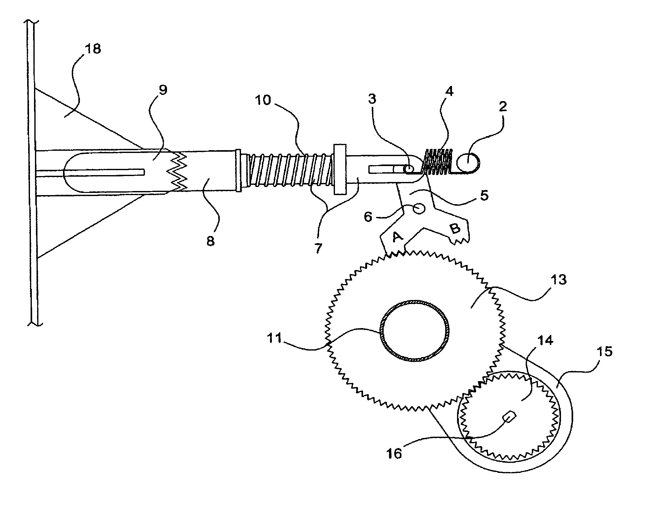
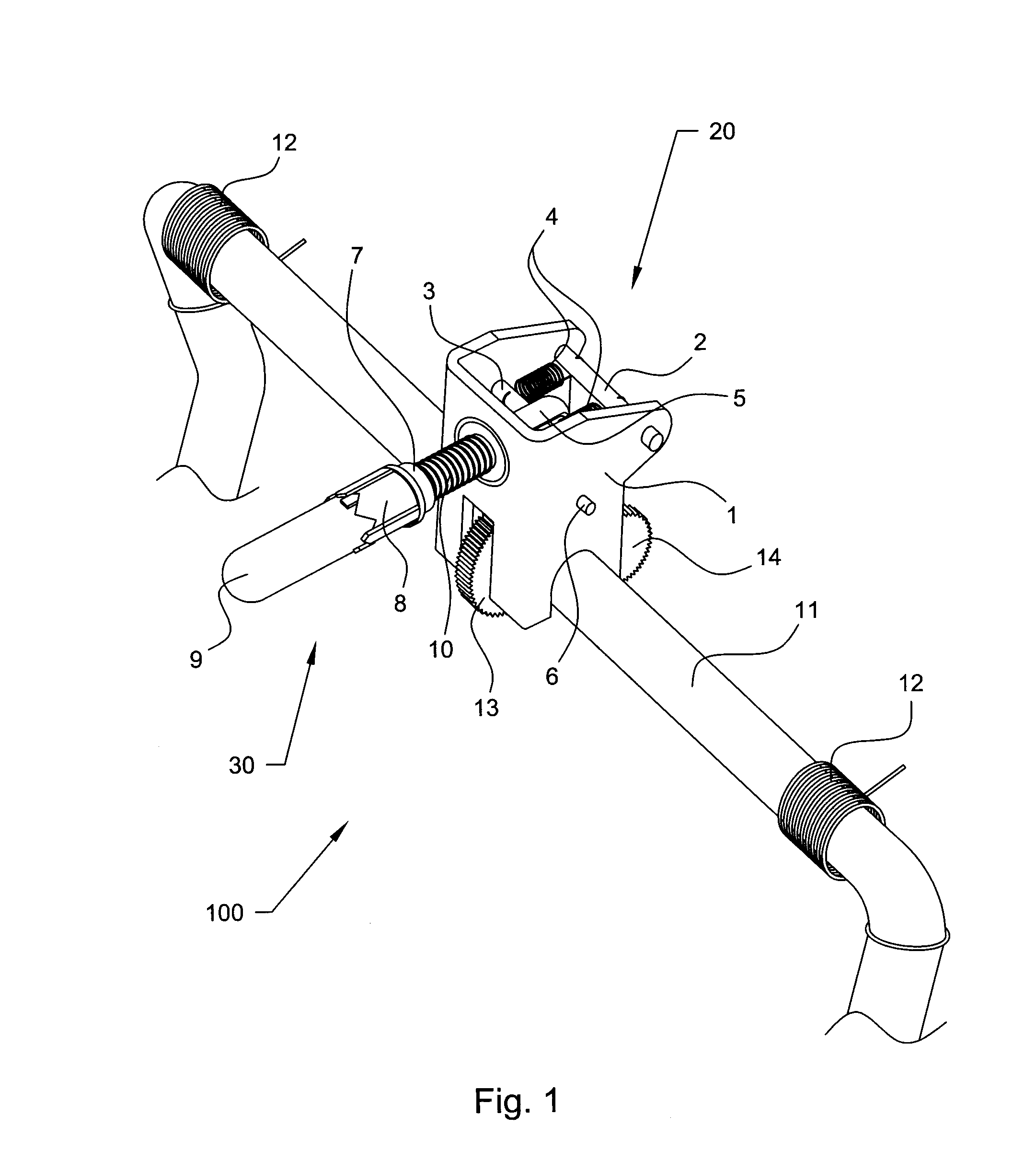
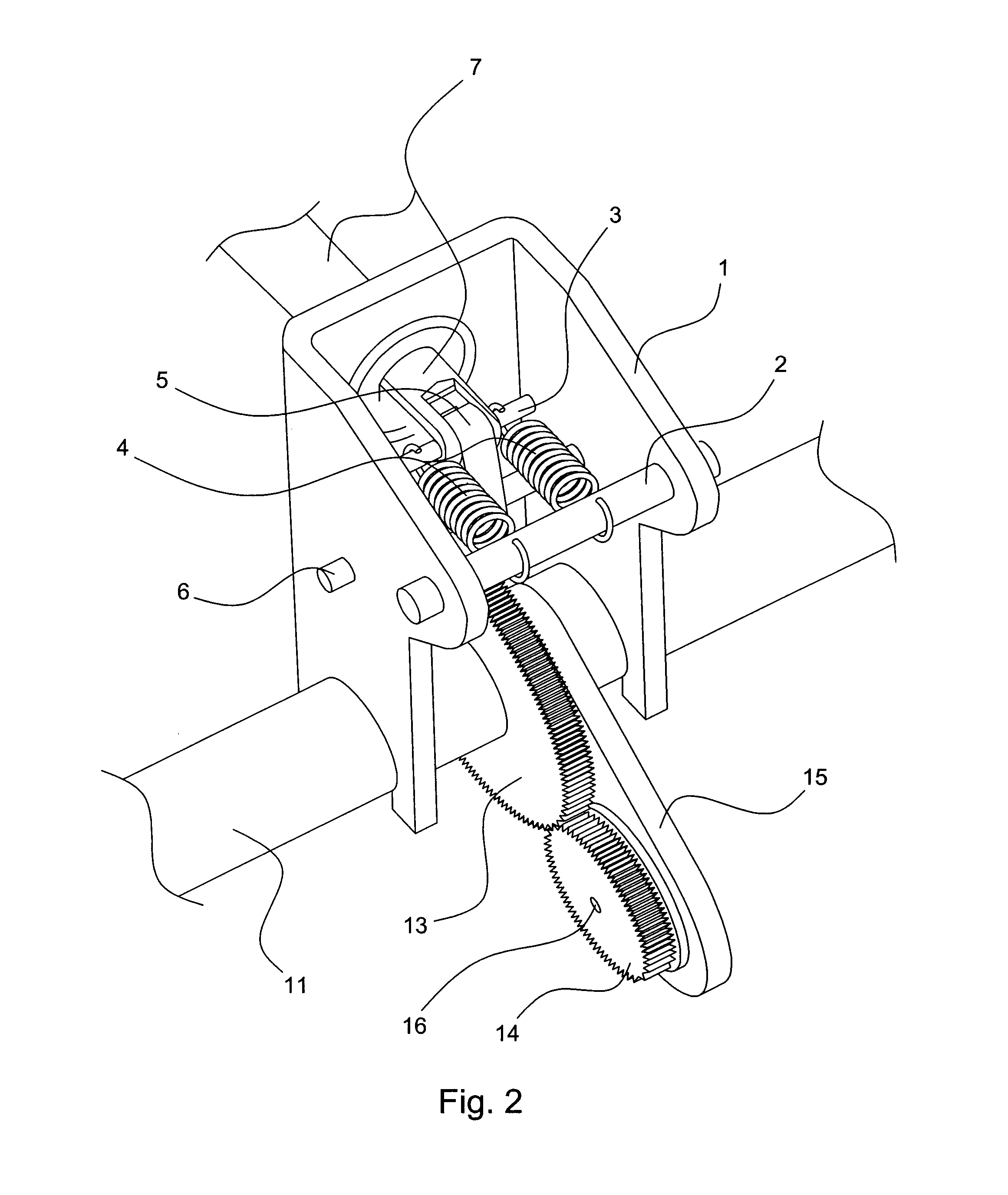
[0021]Reference will now be made to the drawings, wherein to the extent possible like reference numerals are utilized to designate like components throughout the various views. Generally, the present invention discloses an adjustable head restraint assembly constructed according to a presently preferred embodiment of the invention generally shown at 100 in FIG. 1 and includes a head restraint body mounted to mounting post 11 for attachment to a seat (not shown). The mounting post 11 is a generally U-shaped support having a pair of spaced apart and parallel extending legs integrally joined at their upper ends by a generally horizontal transverse cross member portion. The mounting post 11 is constructed from a single piece of cylindrical metal rod or cylindrical metal tube having a generally circular cross section which has been bent into the U-shape to form the legs and cross member. The legs are formed on their rearward side with a plurality of notches which are designed to engage a...


PUM


Abstract

A tilt-adjustable head restraint assembly includes a hollowed head restraint body pivotally connected to a U-shaped mounting post. A ratcheting mechanism is disposed within the head restraint body and includes a ratchet interacting with a rack of ratchet teeth. The ratchet has an inertia gear engaged therewith to slow the forward movement of the pivoting head restraint when the ratchet is engaged to allow forward movement of the head restraint, and further has a plunger mechanism which allows for the pivoting of the head restraint in a hands free manner by the application of a static force or pressure.

Description

BACKGROUND OF INVENTION[0001]1.Field of the Invention[0002]The present invention generally relates to an adjustable head restraint for use with a seat such as, for example, a vehicle seat, particularly to such head restraints having a ratcheting mechanism for controlling the angular position of the head restraint. More particularly the present invention is directed to a head restraint which may be easily adjusted in both forward and rearward directions without the use of the occupant's hands.[0003]2. Description of the Related Art[0004]Various head restraints are known to the art which include a head restraint body pivotally coupled to a mounting post for enabling the head restraint body to pivot in a forward and rearward direction to achieve a desired position of angular adjustment chosen by the user. Such head restraints are also known to include various ratcheting détente mechanisms which allow the head restraint to pivot forwardly but limit its rearward pivotal movement for safe...

Claims


Application Information

Patent Timeline
Patent Type & Authority Patents(United States)
IPC IPC(8): B60N2/48
CPCB60N2/4841B60N2/841
Inventor LOW, KAR KEONGYETUKURI, NAGARJUN V.MCQUEEN, KENNETH J.SEBBY, MARK S.GASPAROTTO, KEVIN L.
Owner LEAR CORP
Why Eureka
Try Eureka