
Compensation of lateral position changes in printing

a technology of lateral position change and printing, which is applied in the field of compensating lateral position change in printing, can solve the problems of lateral misalignment of individual images, one or more nozzles, and an issue of interest in registration accuracy, and achieve the effect of effective dot-forming-element redundancy, effective dot-forming-element redundancy, and effective dot-forming-element redundancy

Active Publication Date: 2005-09-13
HEWLETT PACKARD DEV CO LP
View PDF11 Cites 22 Cited by
  • Summary
  • Abstract
  • Description
  • Claims
  • Application Information

AI Technical Summary

Benefits of technology

The patent describes a printing device that can compensate for errors in dot-forming elements and distribute the activity of these elements between multiple print stations. The device includes a controller that uses print masks to compensate for errors and a lateral-position detector to indicate the relative position of the recording medium during printing. The device can also include a print-mask memory to store print masks for different positions in the medium. The technical effect of this invention is to improve the accuracy and efficiency of printing images on a moving recording medium.

Problems solved by technology

With the increasing resolution of modern printers the registration accuracy has become an issue of interest.
However, small movements in a direction perpendicular to that may cause a lateral displacement of the recording medium from one print station to the other and, accordingly, a lateral misalignment of the individual images.
Due to large numbers of dot-forming elements (nozzles) in the print station, generally one or more of the nozzles will be defective.

Method used


Image

  • Compensation of lateral position changes in printing
  • Compensation of lateral position changes in printing
  • Compensation of lateral position changes in printing

Examples


Embodiment Construction

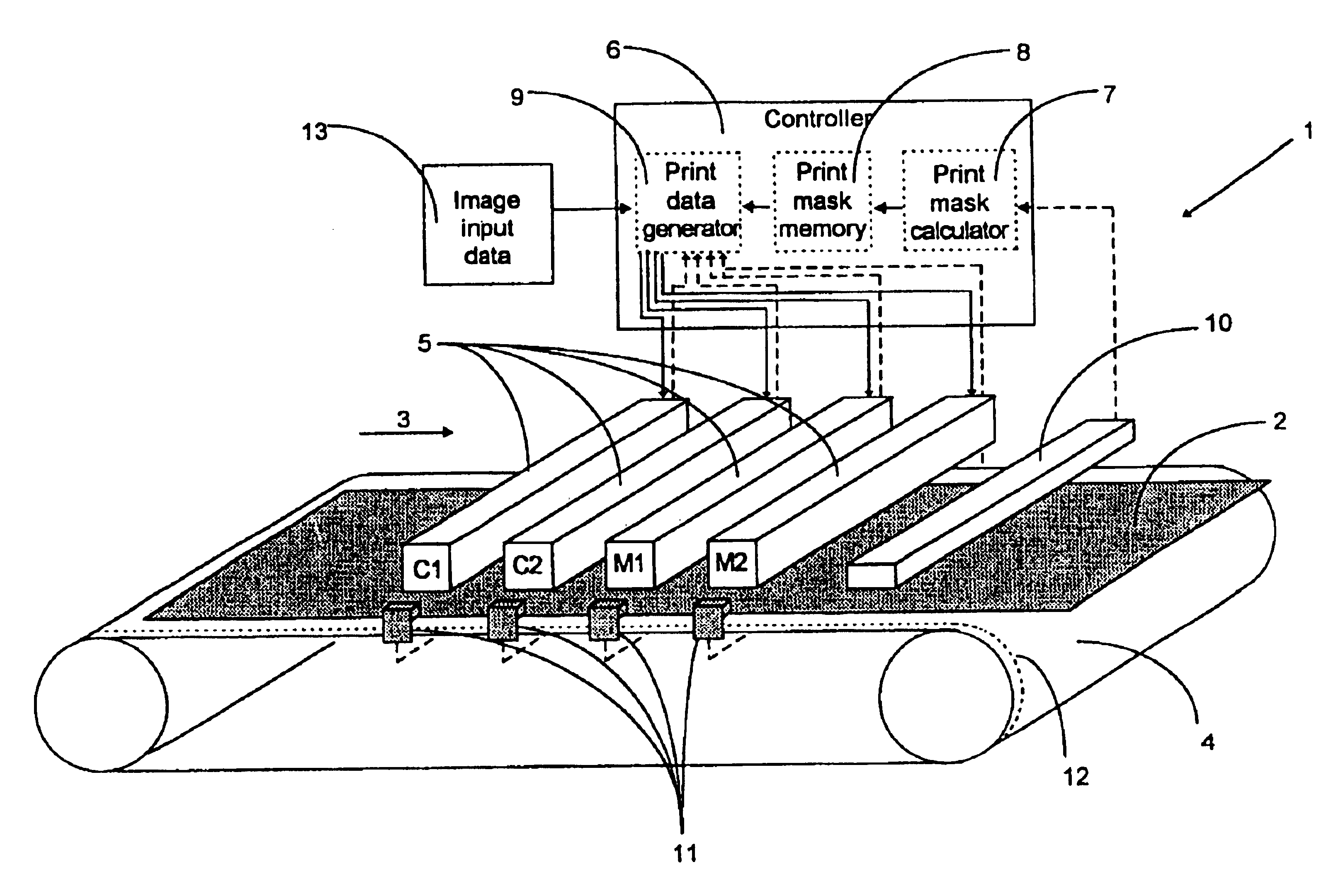
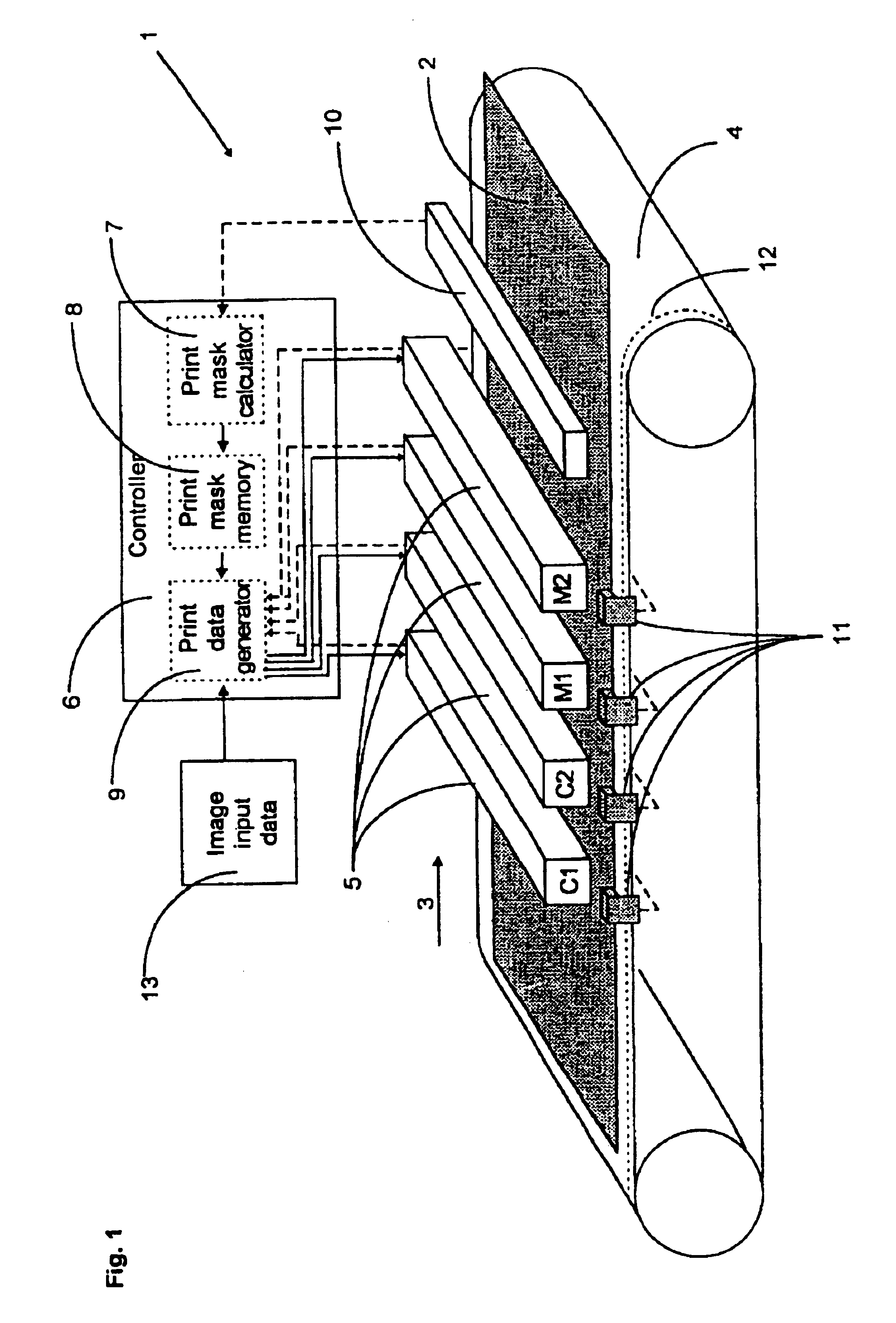
[0024]FIG. 1 illustrates an embodiment of a printing device. Before proceeding further with the detailed description of FIG. 1, however, a few items of the embodiments will be discussed.

[0025]In some of the embodiments, the printing device is equipped with a plurality of print stations which are successively passed by the recording medium conveyed by a conveyor (e.g., a belt) during a print process. The print stations are arranged to print single-color images. In embodiments enabling multi-color images to be printed, each print station prints a part of the entire multi-color image. The printing is based on input image data virtually separated into data representing the individual image parts printed by the respective print stations. A multicolor image is typically separated into four single-color images (the separation is, for example, based on the basic colors cyan, magenta, yellow and black). As will be explained below, the print stations have dot-forming elements (e.g. nozzles) w...


PUM


Abstract

A printing device has a plurality of print stations including dot-forming elements arranged to produce an image on a moving recording medium and provided in a redundant manner, thereby enabling dot-forming-element activity to be distributed between redundant dot-forming elements and errors of dot-forming elements to be compensated. A lateral-position detector arrangement or predictor is arranged to indicate the recording medium's lateral position relative to the print stations during a print process. A controller is arranged to use at least one print mask for each print station to distribute the dot-forming-element activity between the print stations and to compensate the errors of dot-forming elements. The printing device is arranged so that, in response to a detected or predicted change of the relative lateral position, at least one of the currently used print masks is replaced by another one relating to the changed relative lateral position.

Description

FIELD OF THE INVENTION[0001]The present invention relates to compensation of lateral position changes in printing and, for example, to a method of compensating lateral position changes of a moving recording medium during a print process and to a printing device.BACKGROUND OF THE INVENTION[0002]Multicolor printers generate images which are composed of a plurality of different single-color images. The quality of the final multicolor image depends on the accuracy of the alignment of the individual images (also called “registration accuracy”). With the increasing resolution of modern printers the registration accuracy has become an issue of interest.[0003]Different printing techniques are known. For example, in ink-jet printing droplets of liquid ink are directed from print heads towards a recording medium. Each print head has a plurality of ink channels. Pulses cause droplets of ink to be expelled as required from dot-forming elements in the form of orifices or nozzles at the end of th...

Claims


Application Information

Patent Timeline
Patent Type & Authority Patents(United States)
IPC IPC(8): B41J11/00B41J2/21
CPCB41J2/2139B41J2/2146B41J2/2135B41J11/0095B41J11/008B41J2025/008
Inventor MOLINET, PEP-LLUISSOLER, XAVIERLOPEZ, MANUEL
Owner HEWLETT PACKARD DEV CO LP
Learn More