
Light fighter lethality seeker projectile

a projectile and light fighter technology, applied in the field of weapons, can solve the problems of unsatisfactory potential solutions, high probability of hitting (by fragments) against stationary targets, and inability to improve the hit probability against targets which continue to mov

Inactive Publication Date: 2005-11-01
UNITED STATES OF AMERICA THE AS REPRESENTED BY THE SEC OF THE ARMY
View PDF18 Cites 34 Cited by
  • Summary
  • Abstract
  • Description
  • Claims
  • Application Information

AI Technical Summary

Benefits of technology

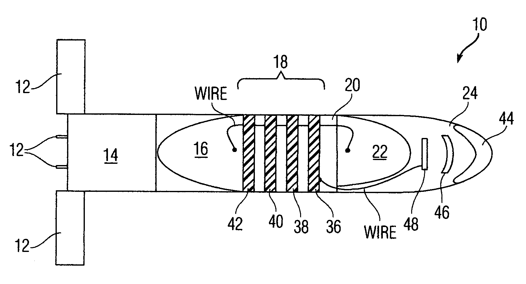
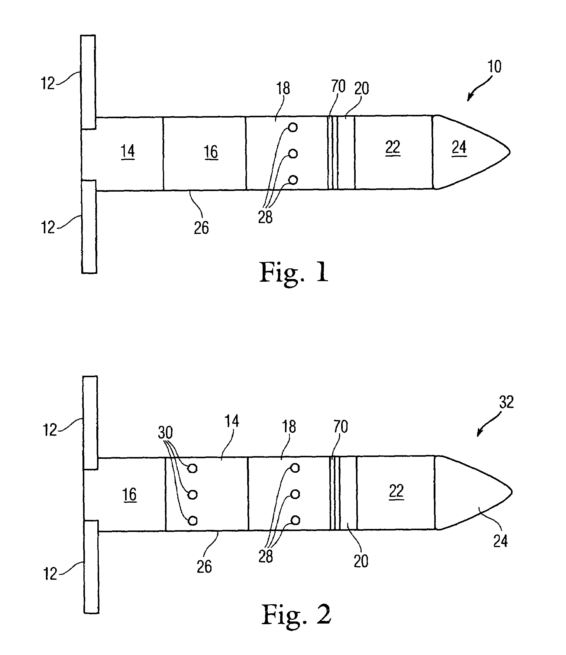
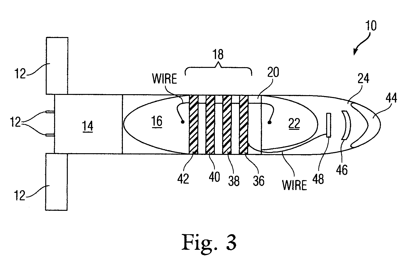
[0015]The LFLSP compensates for aim error; variations in muzzle velocity, variations in rocket burnout velocity, movement of the target after launch, and non-standard atmospheric effects on the trajectory. The projectile contains an imaging seeker (not a hot spot or quadrature seeker) which locates the target with respect to fixed reference points in the target area (reference points provided by the fire control system). The projectile tracks the target, maneuvers to burst near a moving target, recognizes when a target has gone to defilade, and flies to and airbursts over the target's defilade location. The inventive projectile increases the probability of a hit and the probability of a kill.

Problems solved by technology

The introduction of shoulder fired, fragmenting grenades resulted in a higher probability of hit (by a fragment) against stationary targets.
Because a shoulder fired weapon is semi-stabilized at best, this potential solution is not satisfactory.
The use of an automatic target tracker together with marking a target's last observed position in image space improves hit probability for an airburst fuzed grenade, but does not improve hit probability against a target which continues to move, and does not compensate for the effect of non-standard atmospheric conditions (primarily range and cross wind).
Adding an off-boresight laser range finder to an automatic target tracker improves hit probability for both moving and move to defilade targets by improving the burst time accuracy for airburst fuzed grenades, but fails to compensate for aim error or for the effect of non-standard atmospheric conditions on flight time and deflection.

Method used


Image

  • Light fighter lethality seeker projectile
  • Light fighter lethality seeker projectile
  • Light fighter lethality seeker projectile

Examples


Embodiment Construction

[0012]The present invention is known as the Light Fighter Lethality Seeker Projectile (LFLSP). The LFLSP includes projectile knowledge of the approximate target location on the battlefield at launch. The projectile is provided this information before launch. Using this target location, the fire control system also calculates the “did hit” initial trajectory which will intercept the target. The time of flight, components of the projectile position and velocity will be transmitted to the projectile. If the projectile's actual trajectory is different from its ideal trajectory, and would cause the projectile to miss the basket to acquire the target downrange then the guidance and control system will initiate a command to correct the ballistic trajectory. In addition, the projectile's imaging seeker is provided with what it will see when it turns on down range, in particular, the location of the target in the scene and the target's relationship to conventional points of reference at the ...


PUM


Abstract

A projectile comprises an imaging seeker at a front of the projectile; a front warhead behind the imaging seeker; a power supply; an electronics unit connected to the power supply and comprising a microprocessor circuit board, a voltage regulator circuit board, an inertial measurement circuit board and a fuze and safe and arm circuit board, all electrically connected to each other, the microprocessor circuit board also being connected to the imaging seeker; a rear warhead, the front and rear warheads being electrically connected to the safe and arm circuit board; a rocket motor electrically connected to the electronics unit; foldable fins mounted at the rear of the projectile; a shell that encases the front warhead, the power supply, the electronics unit, the rear warhead and the rocket motor; and a maneuver mechanism disposed in the shell and electrically connected to the microprocessor circuit board.

Description

CROSS REFERENCE TO RELATED APPLICATIONS[0001]This application claims benefit under 35 U.S.C. 119(e) of provisional application 60 / 320,073, filed Apr. 1, 2003, the entire file wrapper contents of which provisional application are herein incorporated by reference as though fully set forth at length.FEDERAL RESEARCH STATEMENT[0002]The inventions described herein may be manufactured, used and licensed by or for the U.S. Government for U.S. Government purposes.BACKGROUND OF INVENTION[0003]The invention relates in general to munitions and, in particular, a gun launched, small caliber, autonomous, seeker assisted, guided projectile.[0004]In the past, infantrymen engaged personnel targets with rifles that fired unguided projectiles. Firing on a moving target with a non-maneuvering projectile resulted in a low probability of hit, while the probability of hit for a target in defilade was zero. The introduction of shoulder fired, fragmenting grenades resulted in a higher probability of hit (by...

Claims


Application Information

Patent Timeline
IPC IPC(8): F42B15/00F42B12/02F42B15/01F42B10/64F42B10/66F42B15/04
CPCF42B10/64F42B10/66F42B15/01F42B15/04
Inventor SADOWSKI, LUCIAN M.CHUNG, SUNG K.WHITESIDE, JOHN H.CINCOTTA, TOMAS
Owner UNITED STATES OF AMERICA THE AS REPRESENTED BY THE SEC OF THE ARMY
Learn More