Method for correction of inertial sensor mounting offsets

a technology of inertial sensor and offset, which is applied in the field of vehicle stability control systems, can solve the problems of inability to mount perfectly and store assembly errors, and achieve the effect of reducing cross-axis mounting errors

Active Publication Date: 2007-06-28
KELSEY HAYES CO
View PDF11 Cites 35 Cited by
  • Summary
  • Abstract
  • Description
  • Claims
  • Application Information

AI Technical Summary

Benefits of technology

[0007] This invention relates to a method to compensate for mounting errors of the inertial sensors used in vehicle stability control systems.
[0008] Regarding cross-axis errors, the root cause of such errors is the mounting of the sensors. It is desirable to mount the sensors perfectly in the intended axis of measurement or to quantify the actual mounting error. However, perfect mounting is not feasible; therefore, the best solution is to quantify the actual mounting errors and store them in a non-volatile memory for use by the VSC control algorithm. An approach for doing this in a VSC system uses multiple accelerometers that measure true lateral and longitudinal acceleration at the time of manufacture. Allowable offset errors due to the manufacturing of lateral and longitudinal accelerometers and an Electronic Control Unit (ECU) in which the accelerometers are mounted are measured with the ECU accelerometers and stored in a non-volatile memory location before being mounted in a vehicle. When the ECU and sensors are mounted in the vehicle, these offsets are communicated to a microprocessor, which contains algorithms for performing VSC. The microprocessor then measures offset errors after installation of the sensors upon the vehicle, and combines the errors with the errors stored in memory from the manufacturing of the sensors and ECU. With this information, and input from other vehicle sensors, the errors due to installation for the sensors on a vehicle can be compensated.
[0009] More specifically, the invention contemplates a method for reducing cross-axis mounting error for an inertial sensor that includes installing the sensor within an electronic control unit that is attached to a hydraulic valve body that is carried by a mounting bracket. The entire assembly is placed upon a test stand and rotated with the sensor actuated to determine any assembly errors due to miss-mounting of sensor within the electronic control unit and / or assembly tolerances. The resulting assembly errors are stored in a non-volatile memory. The assembly is then installed upon a vehicle and the vehicle is placed upon a true surface and the mounting off-set errors are measured. Corrected offset errors are then determined by combining the mounting offset errors with the stored assembly errors. The corrected offset errors are then stored in the non-volatile memory for use with an electronic brake control system.
[0010] The invention further contemplates that prior to installing the sensor within the electronic control unit, the sensor is placed upon a true surface and any offset errors for the inertial sensor relative to the true surface are measured. The offset errors are then stored in the non-volatile memory. The offset errors are later combined with the assembly and mounting offset errors for use with an electronic brake control system.
[0011] The invention further contemplates that prior to mounting upon a vehicle, the sensor is installed within an electronic control unit that is attached to a hydraulic valve body that is carried by a mounting bracket. The entire assembly is placed upon a test stand and rotated with the sensor actuated to determine any assembly errors due to miss-mounting of sensor within the electronic control unit and / or assembly tolerances. The assembly errors are then combined with the stored offset errors and stored for later combination with the corrected offset errors measured after installation upon the vehicle.

Problems solved by technology

Regarding cross-axis errors, the root cause of such errors is the mounting of the sensors.
However, perfect mounting is not feasible; therefore, the best solution is to quantify the actual mounting errors and store them in a non-volatile memory for use by the VSC control algorithm.
The resulting assembly errors are stored in a non-volatile memory.
The offset errors are later combined with the assembly and mounting offset errors for use with an electronic brake control system.

Method used


Image

  • Method for correction of inertial sensor mounting offsets
  • Method for correction of inertial sensor mounting offsets
  • Method for correction of inertial sensor mounting offsets

Examples


Embodiment Construction

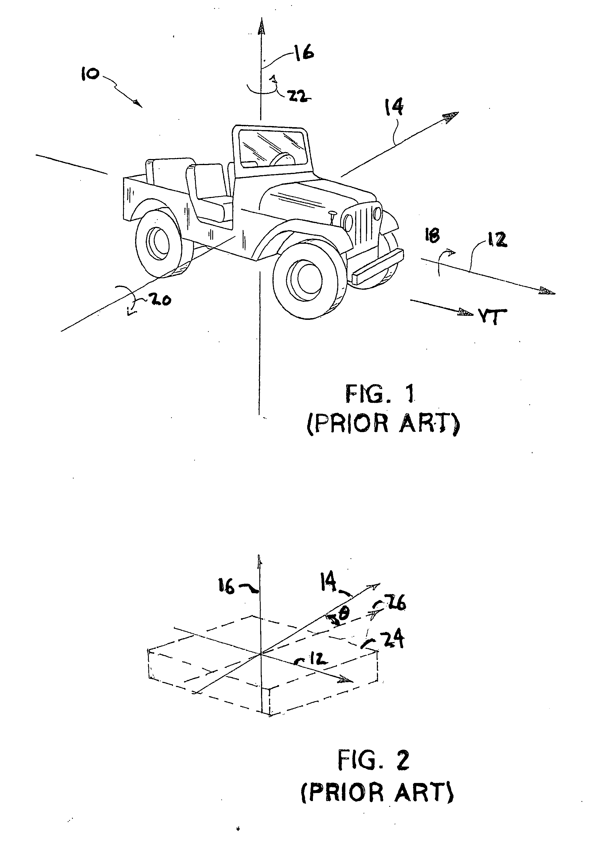
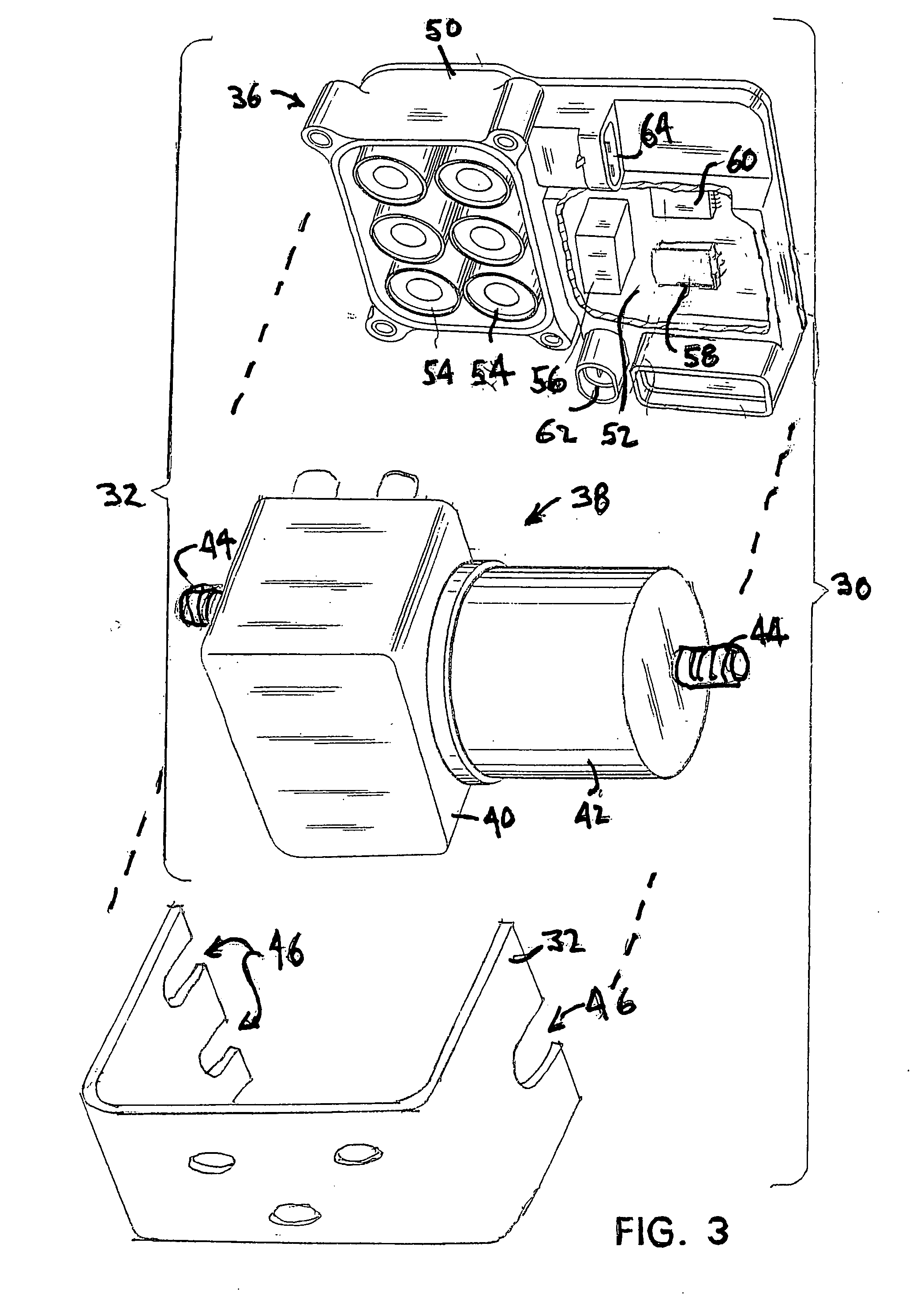
[0021] Referring now to the drawings, there is illustrated in FIG. 3 an exploded perspective view of a Vehicle Stability Control (VSC) System Control Unit assembly 30. The control unit assembly 30 includes hydraulic control unit 32 and a mounting bracket 34 for securing the assembly 30 upon a vehicle, such as the vehicle 10 shown in FIG. 1. The hydraulic control unit assembly 32 is comprised of an electronic control unit 36 that is removably mounted upon a hydraulic valve unit 38.

[0022] The hydraulic valve unit 38 includes a hydraulic valve body 40 upon which is mounted an electric pump motor 42. The motor 42 drives a hydraulic pump (not shown) disposed within the valve body 40. The pump provides pressurized hydraulic fluid to a plurality of solenoid valves (not shown) that are also disposed within the valve body 40. A plurality of ports (not shown) formed in the valve body provide a connection between the solenoid valves and components of the vehicle hydraulic brake system. In the...


PUM


Abstract

A method for calibration of motion sensors included in a vehicle electronic brake control system includes measuring sensor offset errors at different points in the assembly of the system and the vehicle and then combining the offset errors to obtain net offset errors for use with an electronic brake system.

Description

CROSS-REFERENCE TO RELATED APPLICATIONS [0001] This application is a continuation-in-part of International Application No. PCT / US2005 / 031292, filed Aug. 31, 2005, which claims priority from Provisional Patent Application No. 60 / 605,735, filed Aug. 31, 2004. The disclosures of both applications are incorporated herein by reference.BACKGROUND OF THE INVENTION [0002] This invention relates in general to vehicle stability control systems and in particular to a method to compensate for mounting errors of the inertial sensors used in vehicle stability control systems. [0003] Performing vehicle stability control (VSC) with an electronic control unit (ECU) requires accurate inputs of the vehicle's inertial state. This is accomplished with a sensor for detecting and measuring vehicle rotation about a vertical axis, that is, a yaw rate sensor, and either a single lateral accelerometer or a lateral accelerometer and a longitudinal accelerometer. Regardless of how many accelerometers are utiliz...

Claims


Application Information

Patent Timeline
Patent Type & Authority Applications(United States)
IPC IPC(8): G01M19/00G01M99/00
CPCB60T2250/06B60T2250/062G01C21/16G01C25/005G01P1/00G01P15/18G01P21/00B60T8/368G01C21/188
Inventor BABALA, MIKEFONTENOT, KEVIN
Owner KELSEY HAYES CO
Why Eureka
Try Eureka