Ionospheric error prediction and correction in satellite positioning systems

a satellite positioning system and error prediction technology, applied in the field of satellite positioning systems, can solve the problems of denying full system accuracy to non-authorized users, affecting the performance affecting the accuracy so as to reduce the frequency of message transmission and accurate determine the position of the sps receiver

Inactive Publication Date: 2005-07-07
MATSUSHITA ELECTRIC WORKS LTD +1
View PDF12 Cites 38 Cited by
  • Summary
  • Abstract
  • Description
  • Claims
  • Application Information

AI Technical Summary

Benefits of technology

[0025] This invention provides a way for satellite positioning systems (“SPS”) to more accurately determine a SPS receiver's position with less frequent message transmission compared to conventional way of SPS receivers. A SPS system having a GPS receiver and a GPS server compensates for ionospheric errors by receiving ionospheric information at periodic times coinciding with ionospheric events such as sunrise, noon and sun set. The compensation information is sent to a GPS receiver at predetermined events, such as power up, sunrise, noon, and sun set. The GPS receiver then may use other error correction methods in addition to ionospheric error correction when determining the position of the GPS receiver.

Problems solved by technology

This omission allows DoD to control the information broadcast by the satellite and, thus, denies full system accuracy to non-authorized users.
Finally, SD denies access to the GPS signal to unauthorized users in regions of interest by utilizing ground-based jammers.
Unfortunately, SPS includes several types of errors that typically degrade the performance of the SPS receiver.
These errors include random errors and systematic errors that may originate at the satellites, the SPS receiver or be the result of signal propagation errors.
The errors originating at the satellites include ephemeris, orbital, satellite clock, and in the case of GPS, the systematic error caused by the SA, S-A and / or SD selections.
The errors originating at the receiver include; receiver clock errors, multipath error, receiver noise, and antenna phase center variations.
The signal propagation errors are the result of atmospheric refraction that includes delays of the SPS signal as it passes through the ionospheric and tropospheric layers of the atmosphere.
Bending is known to typically cause negligible range errors (particularly if the satellite elevation angle is greater than 5 degrees); however, the change in propagation speed is known to cause significant range errors because the ionosphere speeds up the propagation of the carrier phase beyond the speed of light while slowing down the PRN-code by the same amount.
Additionally, the ionosphere causes a delay that is frequency dependent such that the lower the frequency, the greater the delay.
As an example, the ionospheric delay of a transmitted SPS signal may cause an error of approximately ten meters when calculating the position of the SPS receiver.
Unfortunately, DGPS is not always available and even when it is it may still take a relatively long time to determine an acceptable position accuracy at the mobile SPS receiver because the mobile SPS receiver needs to receive the differential data from the SPS server.
However, this differential data is only the error information observed at the SPS server not the mobile SPS receiver.
As the distance between the mobile SPS receiver and SPS server increases, the error information observed at the SPS server becomes less useful.
Additionally, now that SA has been turned off by DoD, ionospheric and multipath errors have become the most prominent errors.
Unfortunately, conventional DGPS schemes continue to perform numerous costly communications between the mobile SPS receiver and SPS server.
Moreover, when the communication link is unstable (such as in a wireless system) or unavailable the benefits of DGPS drop of significantly.
Unfortunately, the TEC model described in ICD-GPS-200 still results in significant ionospheric errors because ICD-GPS-200 treats both DC and σ as constant values while the actual TEC values of the ionosphere is difficult to model.

Method used


Image

  • Ionospheric error prediction and correction in satellite positioning systems
  • Ionospheric error prediction and correction in satellite positioning systems
  • Ionospheric error prediction and correction in satellite positioning systems

Examples


Embodiment Construction

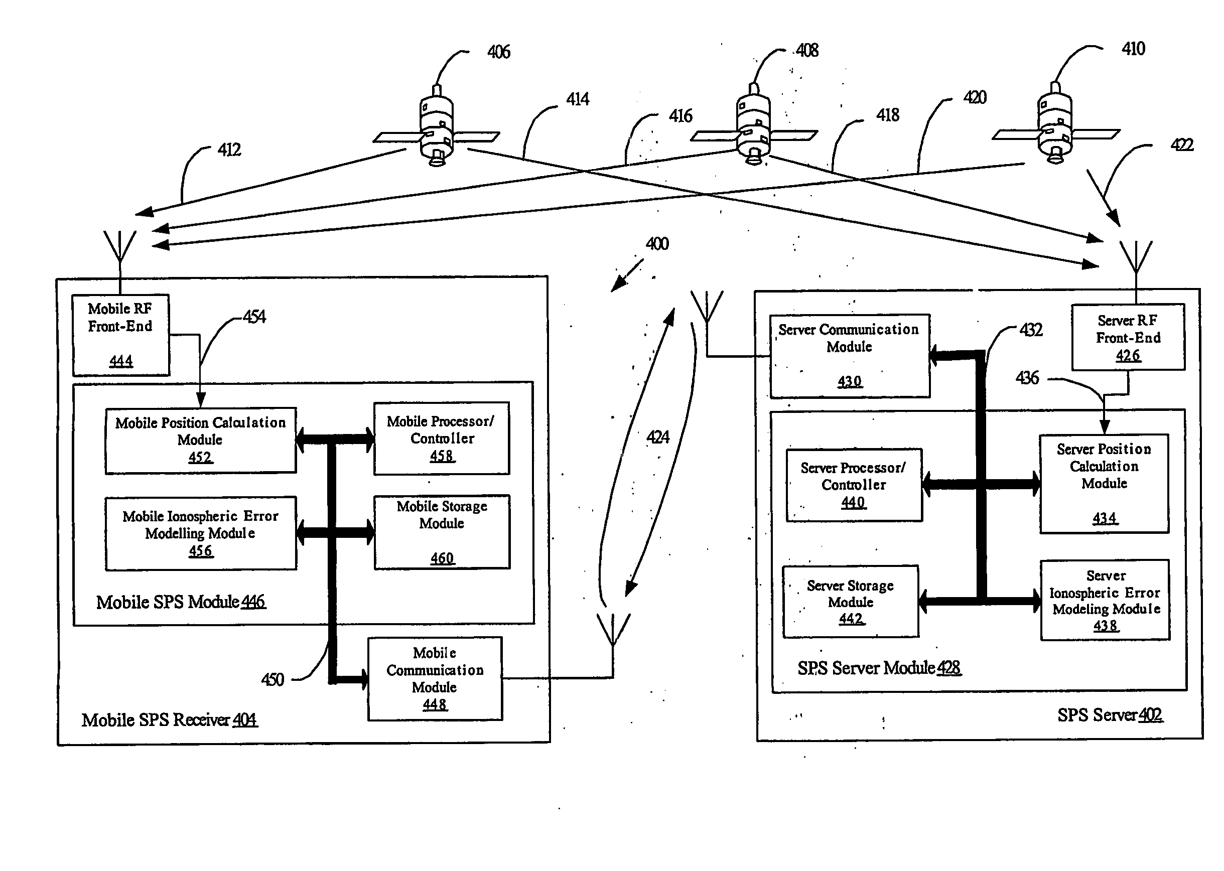
[0037] In FIG. 4, a satellite positioning system (“SPS”) for predicting and compensating for ionospheric errors (“SPSPC”) 400 is shown having a SPS server 402 and a mobile SPS receiver 404. Both the SPS server 402 and mobile SPS receiver 404 are in signal communication with various SPS satellites 406, 408 and 410 via signal paths 412, 414, 416, 418, 420 and 422, respectively. Additionally, the SPS server 402 is in signal communication with the mobile SPS receiver 404 via signal path 424.

[0038] The SPS server 402 may include a server radio frequency (“RF”) front-end. 426, a SPS Server Module 428, a Server Communication module 430 and a SPS server bus 432. The SPS Server Module 428 may include a Server Position Calculation Module 434 in signal communication with the RF front-end 426, via signal path 436, a Server Ionospheric Error Modeling Module 438, Server Processor and / or Controller 440 and Server Storage Module 442. The Server Ionospheric Error Modeling Module 438, Server Process...


PUM


Abstract

A GPS server capable of receiving information for use in determining ionospheric errors using mathematical formulas and sending ionospheric error correction information to GPS receivers that are in a location capable of receiving the ionospheric error correction information.

Description

CROSS-REFERENCE TO RELATED APPLICATIONS [0001] This application claims the benefit of U.S. Provisional Patent Application Ser. No. 60 / 357,157, titled “IONOSPHERIC ERROR PREDICTION AND CORRECTION IN SATELLITE POSITIONING SYSTEMS,” filed on Feb. 13, 2002, which is incorporated herein by reference.BACKGROUND OF THE INVENTION [0002] 1. Field of the Invention [0003] This invention relates generally to satellite positioning systems (“SPS”) devices, and in particular to ionospheric error predication and correction in an SPS. [0004] 2. Related Art [0005] Satellite positioning systems (“SPS”) are satellite-based navigation systems. Examples of SPS include but are not limited to the United States (“U.S.”) Navy Navigation Satellite System (“NNSS”) (also know as TRANSIT), LORAN, Shoran, Decca, TACAN, the Joint Program Office (“JPO”) Global Positioning System (“GPS”) (also known as NAVSTAR, which was developed by the U.S. Department of Defense (“DoD”) in the early 1970s), the Russian counterpart...

Claims


Application Information

Patent Timeline
Patent Type & Authority Applications(United States)
IPC IPC(8): G01S19/38G01S1/00G01S5/14G01S19/07
CPCG01S19/07G01S19/072
Inventor PANDE, ASHUTOSHSUZUKI, JUNICHI
Owner MATSUSHITA ELECTRIC WORKS LTD
Why Eureka
Try Eureka