Optical fiber coupler reinforcing member and optical fiber coupler

a technology of optical fiber couplers and reinforcing members, which is applied in the direction of optics, instruments, optical light guides, etc., can solve the problems of brittle section of corner cb>1/b>, damage to the recess of reinforcing members, and loss of coupling section function, etc., to achieve high reliability and low cost

Inactive Publication Date: 2005-09-13
YAMAHA CORP +1
View PDF9 Cites 9 Cited by
  • Summary
  • Abstract
  • Description
  • Claims
  • Application Information

AI Technical Summary

Benefits of technology

[0030]According to this invention, since the optical fiber coupler comprises the optical fiber coupler reinforcing member according to the above-menti...

Problems solved by technology

In addition, the coupling sections are extremely fine compared with the normal optical fiber and are deformed or break simply due to the application of slight external forces, and there is a risk that the function of the coupling section will be lost.
However, according to the above-mentioned conventional technology, for the reinforcing member comprising the approximately rectangular member having a square bracket-shaped cross-section (hereinafter referred to as the first conventional technology), when a force F is applied from the outer wall surface W1 toward the wall surface W2 of the recess, that force becomes concentrated on the corner C1 formed by the wall surface W2 and the bottom surface W3 of the recess, and therefore, there is a problem that the section of corner C1 becomes brittle, and the recess of reinforcing member A is damaged (refer to FIG.
However, with the above-mentioned second conventional technology, there is a problem that it is not easy to keep the reinforcing member B stationary on a flat work bench, and the working efficiency of housing the coupling section of the optical fiber coupler within the recess is remarkably reduced (refer to FIG.
In addition, with respect to flat-surface processing and curved-surface processing, the cost of curved-surfac...

Method used


Image

  • Optical fiber coupler reinforcing member and optical fiber coupler
  • Optical fiber coupler reinforcing member and optical fiber coupler
  • Optical fiber coupler reinforcing member and optical fiber coupler

Examples


Embodiment Construction

[0043]In the following, an embodiment of the present invention will be explained with reference to the drawings.

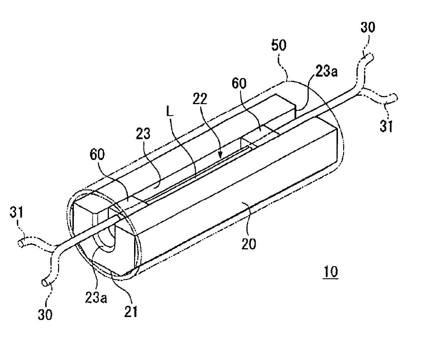
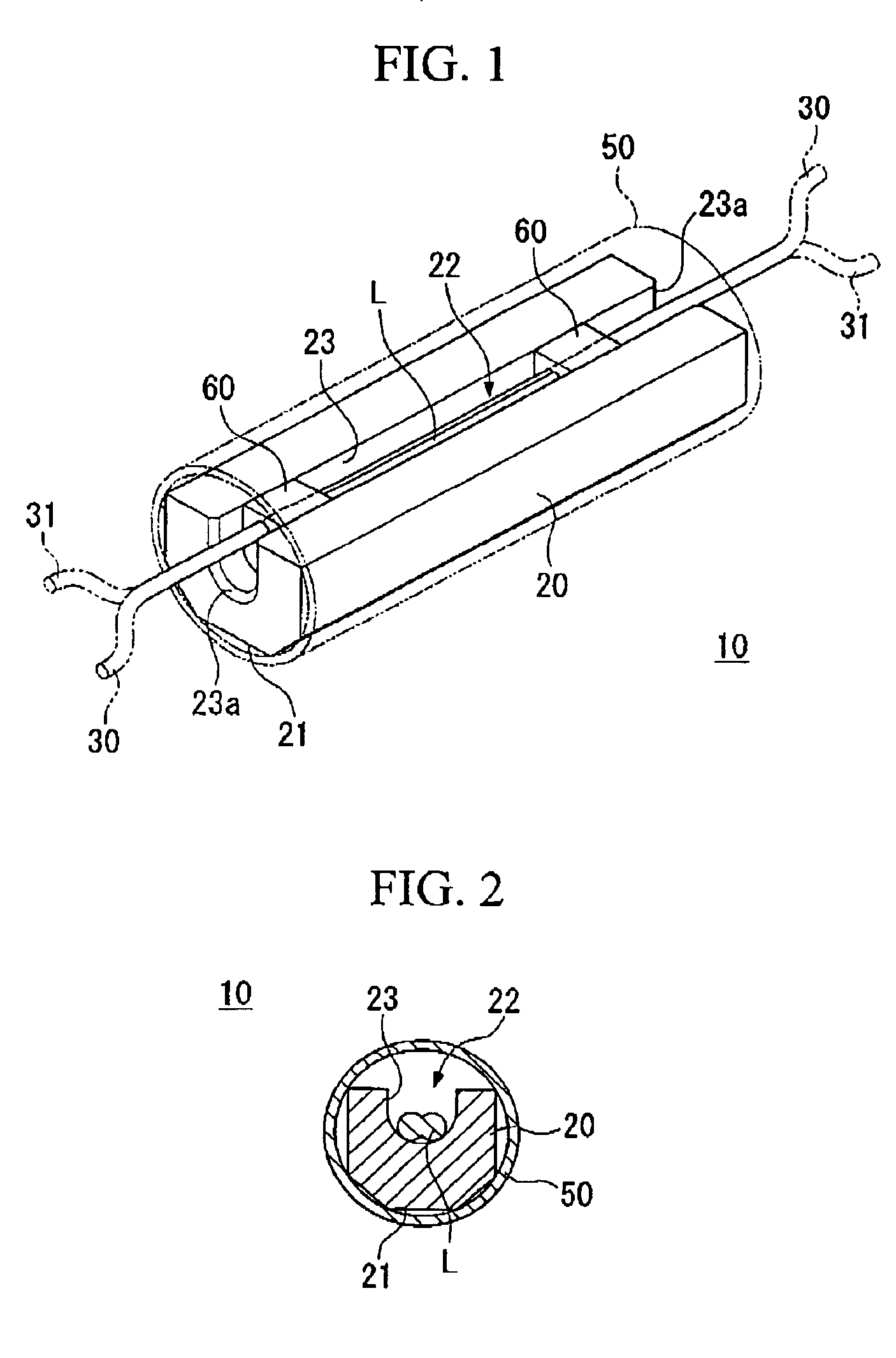
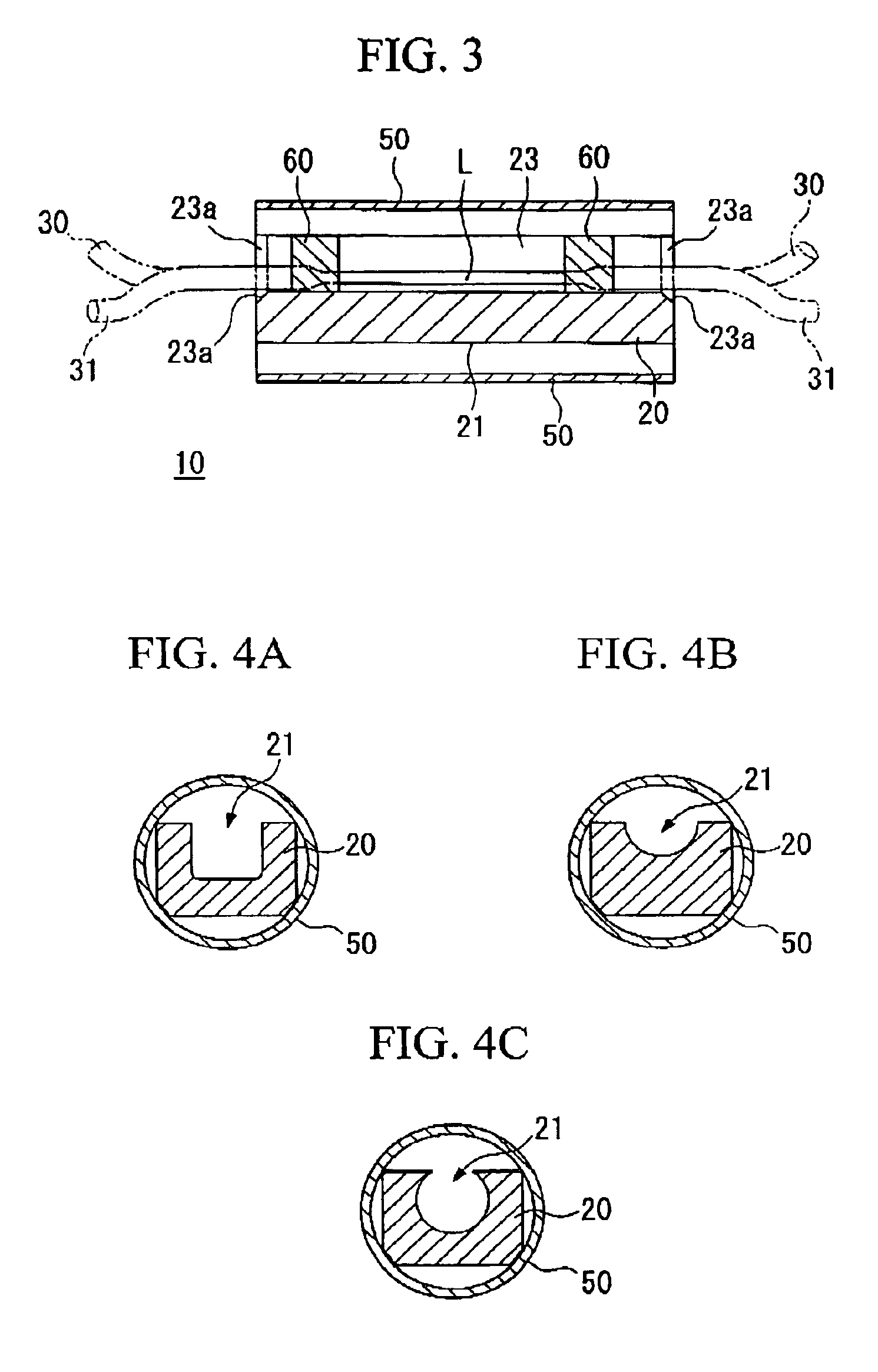
[0044]Each of FIGS. 1 to 3 show the overall constitution of an optical fiber coupler provided with an optical fiber coupler reinforcing member according the present embodiment. FIG. 1 is a perspective view showing the external constitution of an optical fiber coupler according to the present embodiment. FIG. 2 is a cross-section of the optical fiber coupler shown in FIG. 1 along a direction orthogonal to the longitudinal direction thereof. FIG. 3 is a cross-section of the optical fiber coupler shown in FIG. 1 along a longitudinal direction thereof. In these figures, an optical fiber coupler 10 according to the present invention comprises an optical fiber coupler reinforcing member 20 and a coupling section L, in which two optical fibers 30 and 31 are joined, housed within the optical fiber coupler reinforcing member 20, In addition, in this embodiment, the optical fiber co...


PUM


Abstract

An optical fiber coupler reinforcing member comprises an approximately rectangular member formed by a hard material, and has a flat surface along the longitudinal direction thereof. In addition, the shape thereof in cross-section is a hexagonal shape which inscribes a cylindrical member. Furthermore, a recess having a U-shaped cross-section is formed in the longitudinal direction of the above-mentioned approximately rectangular member and houses coupling section. The coupling section housed within the recess is fixed at both ends of the recess by an adhesive or the like. In addition, both ends of the inner wall surface of the recess have been given bevel sections. As a result, the optical fiber coupler reinforcing member having high reliability at low cost, with which the strength with respect to external force is improved and with which processability and the assembly operations of the optical fiber coupler are easy, are provided.

Description

BACKGROUND OF THE INVENTION[0001]1. Field of the Invention[0002]The present invention relates to an optical fiber coupler reinforcing member and to an optical fiber coupler.[0003]2. Description of the Related Art[0004]Optical fiber couplers have a coupling section (the optical fiber coupler main body) which connects a plurality of optical fibers and, at the coupling section, separate or combine the light within the optical fibers. In addition, the coupling sections are extremely fine compared with the normal optical fiber and are deformed or break simply due to the application of slight external forces, and there is a risk that the function of the coupling section will be lost. Therefore, generally, in optical fiber couplers, the coupling section is protected by being housed within a reinforcing member.[0005]As this reinforcing member, conventionally, an approximately rectangular-shaped member having a square bracket-shaped recess (longitudinal groove) in cross-section in which the ...

Claims


Application Information

Patent Timeline
IPC IPC(8): G02B6/36G02B6/28G02B6/287
CPCG02B6/3636G02B6/2821G02B6/28
Inventor TAKEUCHI, NANAYUKIHOSHI, TOSHIHARUIIJIMA, KENZABUROUYASUTAKE, HIDETOSHIISHII, YOSHIKAZUTOMARU, SATORUHWANG, BOOSEOK
Owner YAMAHA CORP
Why Eureka
Try Eureka