Product application device including a dip tube

Inactive Publication Date: 2005-09-13
LOREAL SA
View PDF76 Cites 40 Cited by
  • Summary
  • Abstract
  • Description
  • Claims
  • Application Information

AI Technical Summary

Benefits of technology

[0035]As mentioned above, the invention may be suitable for applying a perfume, which can

Problems solved by technology

As a result, product flowing into the enclosure might tend to generate a pressure rise opposing further ingress of the product.
Thus, when the receptacl

Method used


Image

  • Product application device including a dip tube
  • Product application device including a dip tube
  • Product application device including a dip tube

Examples


Embodiment Construction

[0046]Reference will now be made in detail to exemplary embodiments of the invention, examples of which are illustrated in the accompanying drawings. Wherever possible, the same reference numbers are used in the drawings and the description to refer to the same or like parts.

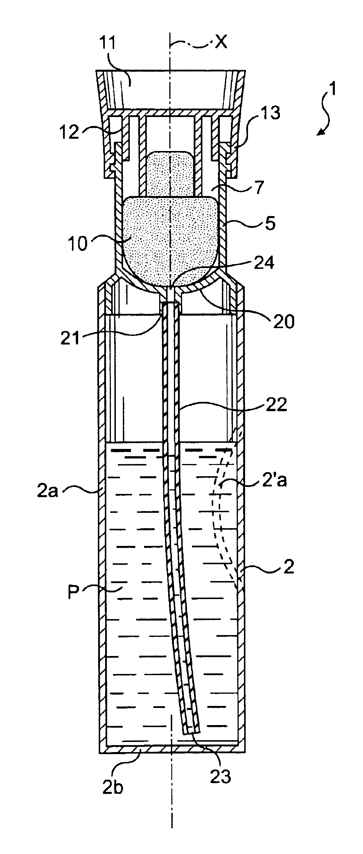
[0047]FIG. 1 shows a packaging and applicator device 1 of the invention, comprising a receptacle 2 having a tubular wall 2a about an axis X and a bottom end wall 2b. The tubular wall 2a may be made of flexible material so as to be elastically deformable. It is thus possible to reduce the inside volume of the receptacle 2 by squeezing the tubular wall, e.g. between finger and thumb, as shown schematically at 2a′.

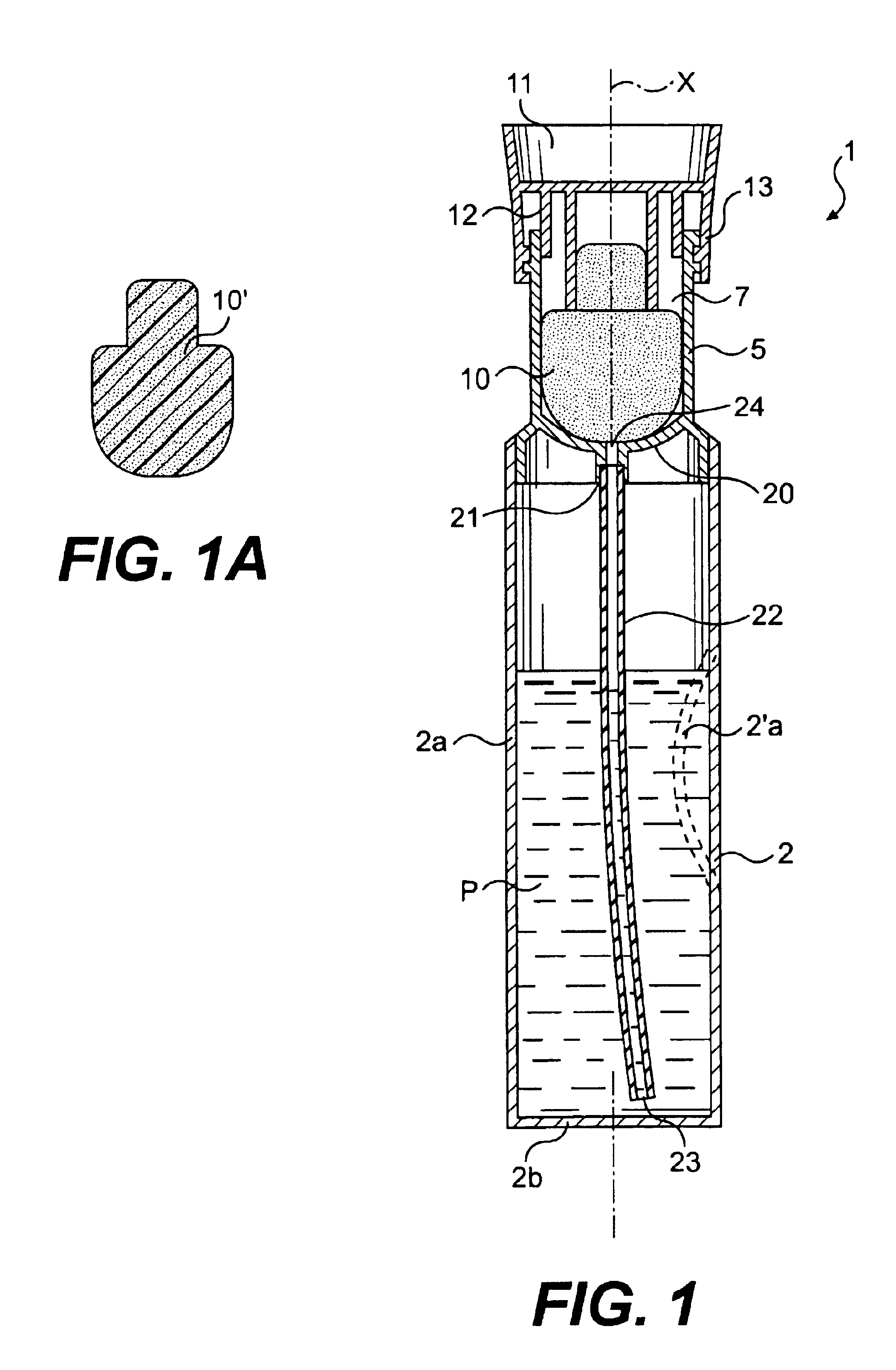
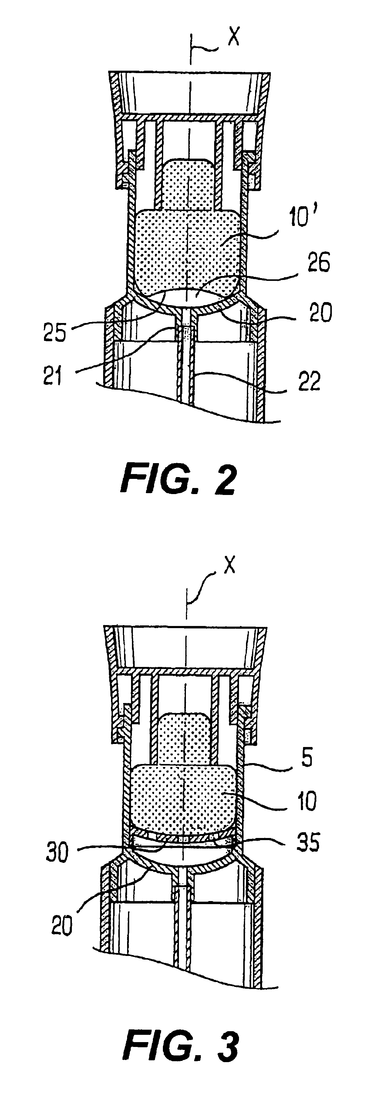
[0048]The receptacle 2 may contain a product P, e.g. a liquid having very low viscosity such as a perfume. The top of the receptacle 2 has a neck 5 defining a housing 7 for receiving an applicator element 10. The applicator element 10 is secured to a handle 11 that also constitutes a cap for substantiall...


PUM


Abstract

A product application device includes a receptacle having a variable inside volume configured to contain a product, an applicator element, and a dip tube configured to extend to the bottom of the receptacle. The device further includes a first portion and a second portion configured to cooperate together to define a substantially leak-proof enclosure for the applicator element. The dip tube is configured to enable the enclosure to be in flow communication with the product flowing from the receptacle.

Description

[0001]The present invention relates to a device for packaging and applying a product, for example, a care product or a cosmetic product such as a perfume. The device may comprise a receptacle configured to contain the product, an applicator element, and a dip tube to allow product to flow from the receptacle to charge the applicator element.DESCRIPTION OF THE RELATED ART[0002]There exists a need for a packaging and applicator device having a structure that is relatively simple, and that enables an applicator element to be filled easily with a relatively large quantity of product. There also exists a need for a device that is capable of containing a product that may have a low viscosity, such as, for example, a perfume, while limiting the risk of leakage in the event of the device being tipped over accidentally.SUMMARY[0003]Optionally, the present invention satisfies one or more needs and / or overcomes one or more shortcomings.[0004]According to an exemplary aspect of the invention, a...

Claims


Application Information

Patent Timeline
IPC IPC(8): A45D34/04B65D47/42B65D47/00B65D51/24B65D51/32A45D40/00A45D40/24A45D34/00B05B11/04B05C17/005B65D47/20B65D83/00
CPCA45D34/045B65D47/42B65D51/32A45D40/24A45D2200/058A45D2200/1018
Inventor GUERET, JEAN-LOUIS H.
Owner LOREAL SA
Why Eureka
Try Eureka