

Catalytically coated particle filter and method for producing the same and its use
a technology of catalytic coating and filter, which is applied in the direction of filtration separation, physical/chemical process catalyst, separation process, etc., can solve the problems of high thermal mass of filters and slow heating of filters, and achieve good ageing stability and sulphur resistance, and high fresh activity
- Summary
- Abstract
- Description
- Claims
- Application Information
AI Technical Summary
Benefits of technology
Problems solved by technology
Method used
Image

Examples
example 1
Filter E1
[0042]To produce a filter according to the invention, the third filter substrate was first of all uniformly coated over its entire length with a platinum catalyst in the same way as in Comparative Example 1. However, the platinum loading was reduced compared to filter C1, to a level of 3.1 g / l (88 g / ft3). Then, to form the first catalyst, what would subsequently be the gas inlet side of the filter was impregnated further over a length of 25.4 mm with 0.42 g / l (12 g / ft3) of palladium using palladium nitrate. The total precious metal content of the filter was therefore likewise 3.18 g / l (90 g / ft3). The first catalyst formed by the further impregnation had a precious metal concentration of 3.53 g / l (100 g / ft3) with a palladium / platinum ratio of 1:7.3. In this case, the second catalyst was formed by the platinum catalyst that had not been impregnated further with palladium. Its palladium / platinum ratio was therefore 0.
[0043]The light-off temperatures of these three filters for ...
example 2
Filter E2
[0050]First of all, the filter substrate was uniformly coated with the platinum catalyst from Comparative Example 1, with a platinum concentration of 3.1 g / l (88 g / ft3). Then, the inlet side of the filter was impregnated further over a length of 25.4 mm with 0.42 g / l (12 g / ft3) of palladium using palladium nitrate. The total precious metal content of the filter was therefore likewise 3.18 g / l (90 g / ft3). The first catalyst formed by the further impregnation had a precious metal concentration of 3.53 g / l (100 g / ft3) with a palladium / platinum ratio of 1:7.3.
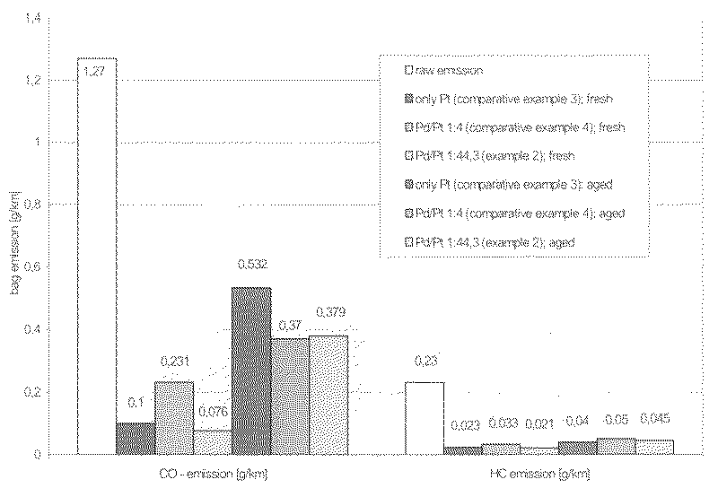
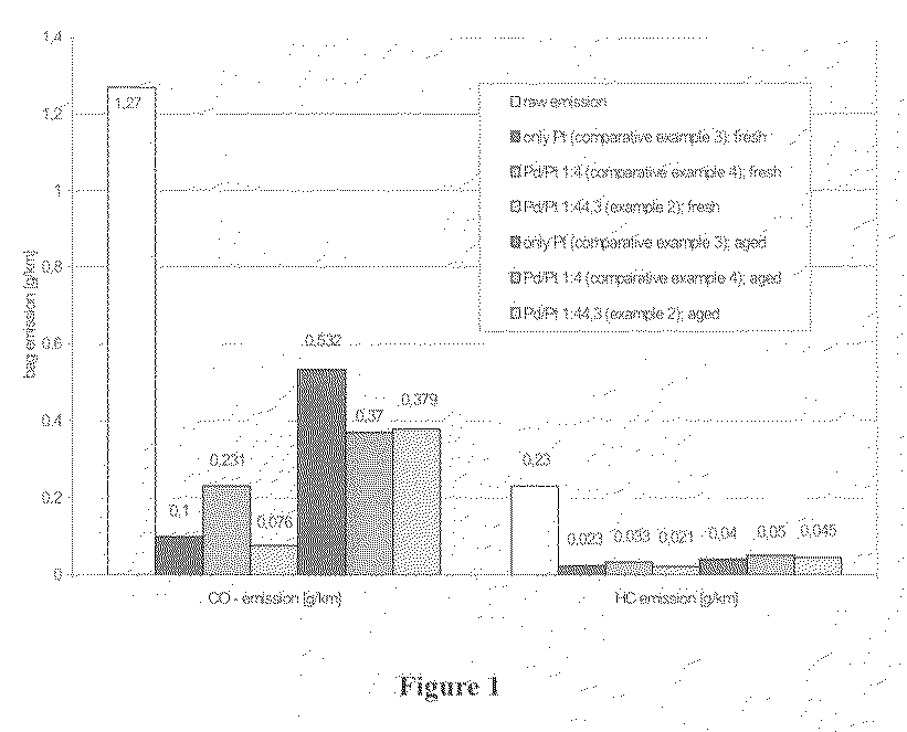
[0051]The testing of the catalytic activity of these filters in the fresh state and after hydrothermal ageing was carried out on a Euro III certified diesel passenger car with a 100 kW 2.2 l diesel engine with common rail. This vehicle was factory-fitted with an oxidation catalyst and a particulate filter. Instead of the light-off temperatures, the emissions in the NEDC driving cycle were determined on the vehicle. For thi...
example 3
[0053]A second set of filters C3, C4 and E2 was produced.
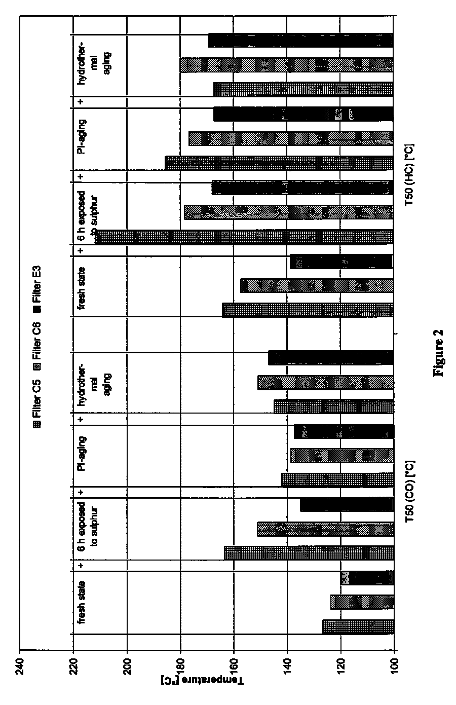
[0054]The filters, without a pre-catalyst, were first of all measured in the fresh state for their light-off temperature at a direct-injection diesel engine (2.2 l capacity) with exhaust gas turbo charging and charge air cooling and a power of 100 kW. Then, all the filters were exposed to sulphur for in each case 6 hours at exhaust-gas temperatures between 200 and 300° C. using a diesel fuel containing 2400 ppm by mass of sulphur and then measured again. The results are compiled in Table 3:
[0055]
TABLE 3Light-off temperatures at the 2.2 1 engine,fresh and after exposure to sulphurFilterPd / PtStateT50(CO) [° C.]T50(HC) [° C.]C10:1freshn.d. (141C21:4fresh133172E21:44.3freshn.d. (147C10:1exposed to sulphur142155C21:4exposed to sulphur171223E21:44.3exposed to sulphur148160
[0056]It is clearly apparent that the filter with the coating comprising only Pt has a similar fresh activity to the filter according to the invention which has be...
PUM
| Property | Measurement | Unit |
|---|---|---|
| pore diameters | aaaaa | aaaaa |
| pore diameters | aaaaa | aaaaa |
| porosity | aaaaa | aaaaa |
Abstract
Description
Claims
Application Information