Motor pump system with axial through flow utilizing an incorporated flowmeter and pressure controller

a technology of axial through flow and motor pump, which is applied in the direction of liquid/fluent solid measurement, application, kitchen equipment, etc., can solve the problem of aberrant electric contact functioning

Inactive Publication Date: 2005-09-13
VERSINI ROLLAND
View PDF14 Cites 45 Cited by
  • Summary
  • Abstract
  • Description
  • Claims
  • Application Information

AI Technical Summary

Benefits of technology

[0013]The pressure controller may comprise a fixed element and an end piece. The fixed element may be coupled to one of the motor pump and a frame supporting the motor pump. The end piece may be mounted to a reservoir. The reservoir may communicate with and provide a supply to the motor pump. The fixed element and the end piece may be releasably coupled together. The fixed element and the end piece may be releasably coupled together via a quick connection.
[0014]The pressure controller may have a fixed element comprising a body, a hollow piece arranged within the body, and two passages separated by the hollow piece. The pressure controller may further comprise an end piece and an axially movable bush disposed within the end piece. The end piece may further comprise a spring associated with the bush which is adapted to close a peripheral passage. The fixed element may be removably coupled to the end piece such that when the fixed element is uncoupled from the end piece, a central passage is closed by a spring actuated valve. The bush may be slidably disposed with the end piece and the fixed element may further comprise a cylindrical shutter which is slidably disposed around the hollow piece. The cylindrical shutter may be biased via a spring. The cylindrical shutter may be adapted to isolate a liquid circuit communicating with the motor pump so as to prevent a liquid remaining in the motor pump from flowing out of the fixed element when the fixed element is uncoupled from the end piece.

Problems solved by technology

Under certain conditions, this arrangement causes an aberrant functioning of the electric contact, in particular during stops and starts of the motor pump.

Method used


Image

  • Motor pump system with axial through flow utilizing an incorporated flowmeter and pressure controller
  • Motor pump system with axial through flow utilizing an incorporated flowmeter and pressure controller
  • Motor pump system with axial through flow utilizing an incorporated flowmeter and pressure controller

Examples


Embodiment Construction

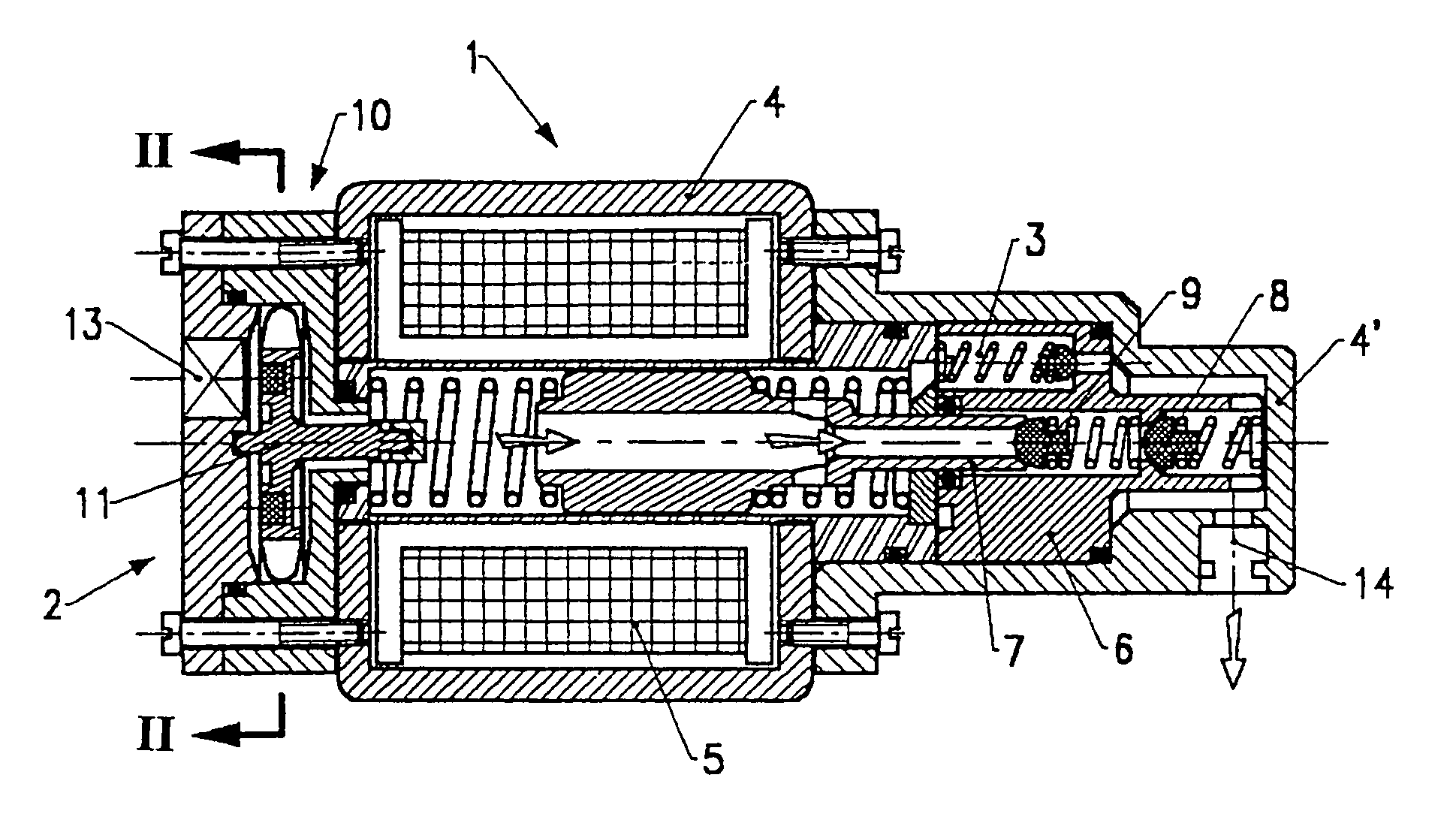
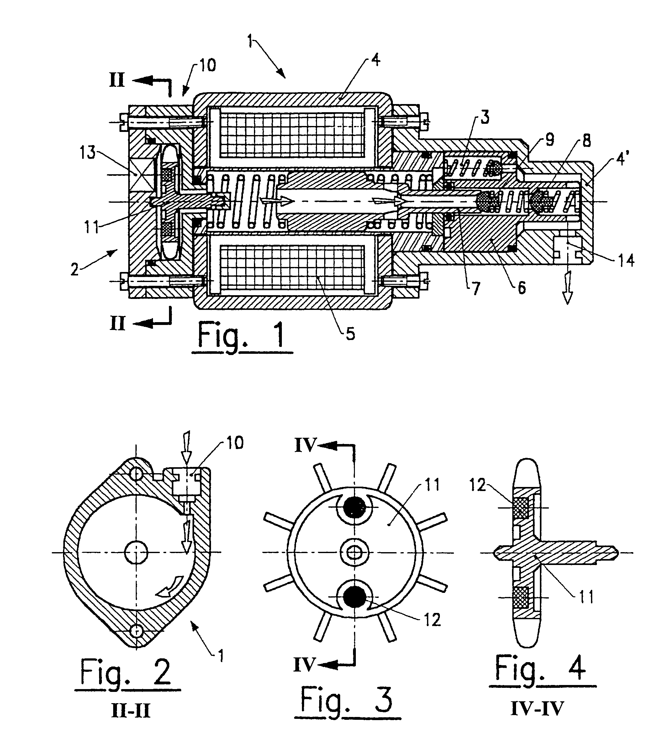
[0025]The device illustrated in FIGS. 1–4, utilizes a liquid supply motor pump 1 having an integral assembly comprising an incorporated flowmeter 2 and pressure limiting device 3. Preferably, it is of the type having a hollow piston with an electromagnetic motor, but it can also be of the type having a controlled piston driven by a rotary engine. In the first case, it is advantageously provided with a main body 4, machined in a single piece made of plastic, one of its ends forming the coil 5 of the electromagnetic motor, the other end containing the cylinder block 6 in which the piston 7 moves, and comprising non-return valves 8 and 9.

[0026]The flow meter 2, located in a block closing the main body 4 on the side opposite the cylinder block 6, immediately after the water inlet 10 (see also FIG. 2), is formed of a free bucket wheel 11 and comprises one or several permanent magnets 12 whose passage is detected by an electromagnetic detector 13, having a double function of allowing the ...


PUM


Abstract

Motor pump system includes an electromagnetic motor comprising a main body, a coil, and a movable hollow free piston. A flow meter is coupled to one end of the electromagnetic motor. A cylinder block is coupled to another end of the electromagnetic motor. At least two non-return valves are included. A water inlet, a water outlet, and a pressure limiting device are also provided. A motor pump system is also provided which includes a motor including main body having an inlet end and an outlet end. A flow meter is coupled to the inlet end. An outlet body is coupled to outlet end. A pressure controller is provided comprising an end piece and a fixed element which is removably coupled to the end piece. The fixed element is coupled to the outlet body.

Description

CROSS-REFERENCE TO RELATED APPLICATIONS[0001]The present application is a National Stage Application of International Application No. PCT / FR99 / 01158, filed May 14, 1999. Further, the present application claims priority under 35 U.S.C. § 119 of French Patent Application Nos. 98 / 06431 and 98 / 10989, both filed on May 15, 1998.BACKGROUND OF THE INVENTION[0002]1. Field of the Invention[0003]The present invention relates to an axial through flow motor pump with an incorporated flowmeter and pressure controller.[0004]The invention is particularly adapted to equip automatic coffee machines, but it can be used for numerous other applications requiring pressurized liquid supply from a reservoir.[0005]2. Discussion of Background Information[0006]The French Patent No. FR 98 06 431 filed by the Applicant of the present invention describes a coffee machine comprising a motor pump associated with a pressure controller mounted on the supply circuit and making it possible not only to control the wat...

Claims


Application Information

Patent Timeline
Patent Type & Authority Patents(United States)
IPC IPC(8): A47J31/44F04B17/03F04B17/04G01F1/05G01F1/075
CPCA47J31/4403F04B17/046G01F1/075
Inventor VERSINI, ROLLAND
Owner VERSINI ROLLAND
Why Eureka
Try Eureka