Plug contact element and a method for manufacturing a housing part for same

Inactive Publication Date: 2005-09-13
DELPHI TECH INC
View PDF8 Cites 4 Cited by
  • Summary
  • Abstract
  • Description
  • Claims
  • Application Information

AI Technical Summary

Benefits of technology

[0023]In the plug contact element in accordance with the invention it is furthermore preferred for the indentation to be asymmetrically formed in relation to a plane which bisects the angle between the wall regions. An indentation formed in this manner has, at least in a convex rounded portion, no tangent which extends orthogonally to the push through direction in the connection region, which reduces the risk of tearing of the edge of the opening. Furthermore, in this way, the area of the indentation can be kept very small. For this it is preferred, in the method in accordance with the invention, for the indentation to be asymmetrically formed in the sheet metal part which is to be bent.
[0024]It is furthermore preferred for the indentation edge to have substantially the shape of a “V” on an at least partly arched surface. In the method in accordance with the invention, it is accordingly preferred for the indentation in the sheet metal part which is to be bent to be substantially V-shaped. The sheet metal part which is to be bent can in this context be in particular planar. This particularly simple shape of the indentation enables a particularly simple pushing into a round opening of a seal, since the indentation edge extends smoothly in the region of the limbs of the “V” and the opening edge can be stretched continuously, i.e. without abrupt changes.
[0025]In this situation, it is particularly preferred for the indentation edge to extend substantially linearly at least in a section on one of the wall regions up to the arched or bent connection region and/or helically in the connection region. This means that, after the bending out of the housing part to a planar part, the indentation edge extends substantially linearly in the wall region and/or along the section which forms the connection region. In accordance with this, it is preferred in the method in accordance with the invention, for the indentation to have a linear edge section in the sheet metal part which is to be bent and for the

Problems solved by technology

When plug contact elements of this kind are pushed through the opening of the seal, the seal however frequently tears at a section of the ope

Method used


Image

  • Plug contact element and a method for manufacturing a housing part for same
  • Plug contact element and a method for manufacturing a housing part for same
  • Plug contact element and a method for manufacturing a housing part for same

Examples


Embodiment Construction

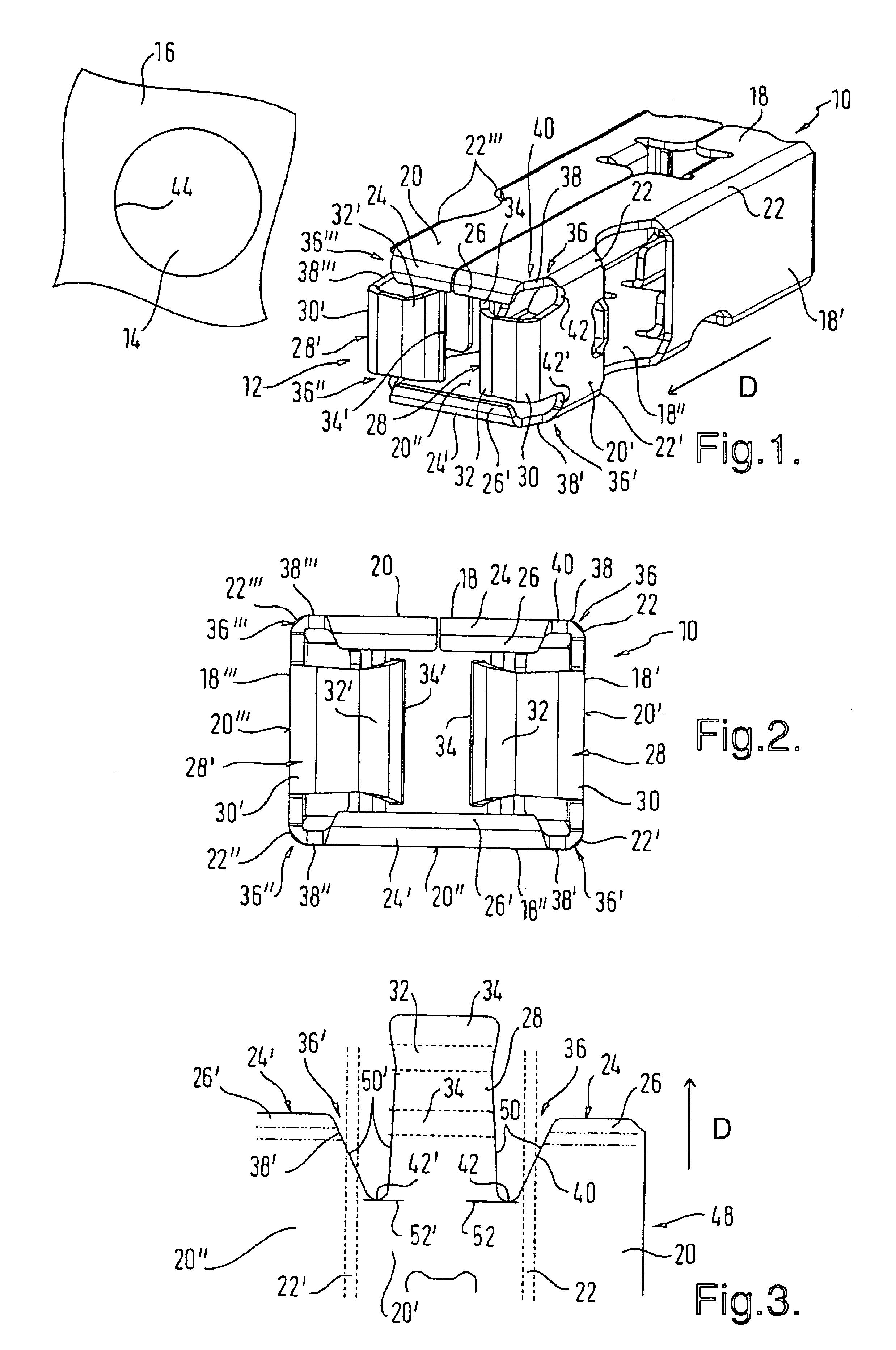
[0041]A plug contact element in accordance with a first preferred embodiment of the invention has an elongate housing part 10 shown in FIGS. 1 and 2 which has substantially the shape of a right parallelepiped and can be pushed with a front side 12 into a circular opening 14 of a seal element 16 along a push through direction D which extends with respect to the longitudinal axis of the right parallelepiped.

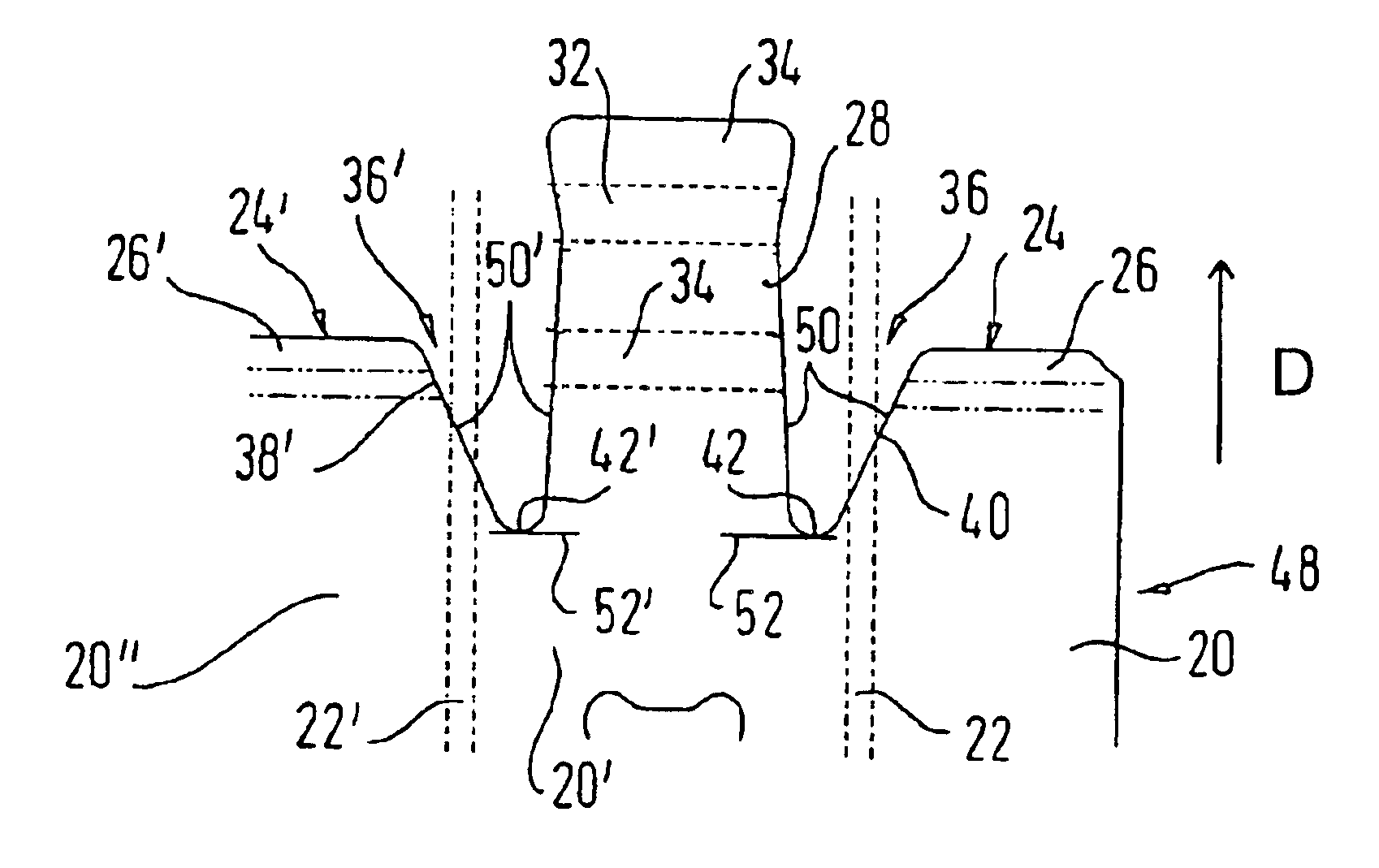
[0042]The housing part 10 has four housing walls 18, 18′, 18′ and 18′″ which extend substantially parallel to the push through direction D and which have planar wall regions 20, 20′, 20′ and 20′″ at the front side 12 which lies in the push through direction. The housing walls and in particular the wall regions are thus mutually inclined at an angle of about 90°. Each of these housing walls 18, 18′, 18′ and 18′″ and thus each of the wall regions 20, 20′, 20′ and 20′″ is connected to two of the other housing walls or wall regions via corresponding bent connection regions 22, 22′, 22′...


PUM


Abstract

The plug contact element for the at least partial pushing through an opening, in particular a round opening, in an elastic material along a push through direction of the plug contact element comprises a housing part having at least two wall regions which are substantially planar and inclined with respect to one another at least at a front side of the housing part and which are connected to one another via an arched or bent connection region, with the housing part having at least one indentation which opens to a front side of the housing part which lies in the push through direction and of which the indentation edge at least partly forms a front-side edge of the arched or bent connection region, with the indentation edge having an apex or a tangent which is orthogonal to the push through direction, the apex or tangent being provided only at the boundary between the connection region and one of the bordering wall regions or at one of the bordering wall regions.

Description

TECHNICAL FILED[0001]The present invention relates to a plug contact element and in particular to a plug contact element for the at least partial pushing through an opening, in particular a round opening, in an elastic material, and to a method for the manufacture of a housing part of a plug contact element of this kind.BACKGROUND OF THE INVENTION[0002]Plug contact elements are known in principle. They serve to connect two electrical leads to one another. For this purpose two mutually complementary plug contact elements, which can be plugged into one another, are electrically and mechanically connected to corresponding ends of the leads. In this arrangement, the plug contact elements as a rule have a mechanically stable, substantially rigid, housing part, which enables a plugging together of the plug contact elements.[0003]In order to at least partly protect a plug contact element of this kind against moisture, it is often pushed through an opening in a seal of an elastic material. ...

Claims


Application Information

Patent Timeline
IPC IPC(8): H01R13/115H01R13/52H01R43/16H01R13/11
CPCH01R13/113H01R13/52H01R43/16
Inventor BRAKE, JENS
Owner DELPHI TECH INC
Why Eureka
Try Eureka