Treatment equipment

a technology for treating equipment and metal blades, which is applied in the field of treatment equipment, can solve the problems of composite blades being scratched in the metal blade holder, heavy weight of metal blade holders, and requiring a load-bearing frame, and achieves the effect of easy retrofitting and simple installation and replacemen

Inactive Publication Date: 2005-09-13
VALMET TECH INC
View PDF4 Cites 32 Cited by
  • Summary
  • Abstract
  • Description
  • Claims
  • Application Information

AI Technical Summary

Benefits of technology

[0017]In the treatment equipment according to the invention, advantageous characteristics are created by the surprising construction and material of the blade holder in the treatment equipment according to the invention. The blade holder is light and is suitable for various kinds of blade. In addition, the blade holder is simple to install and change. Despite the surprising construction, loading members, for example, can also be arranged in the blade holder. The blade holder can also be easily retrofitted to existing treatment equipment, without major alterations. On the other hand, new treatment equipment can be designed to be simpler than before. In addition, by suitable dimensioning and shaping, the components of the treatment equipment can be changed independently of each other, allowing the properties of the treatment equipment to be adjusted precisely as desired.

Problems solved by technology

Metal blade holders are heavy and require a load-bearing frame.
In addition, metal blade holders are rigid, so that they conform poorly to the profile of the surface.
In addition, composite blades become scratched in a metal blade holder during blade changing.
In addition, the attachment devices holding the components of the blade holder together can become detached during use, causing process problems.
The attachment devices also easily gather dirt.

Method used


Image

  • Treatment equipment
  • Treatment equipment
  • Treatment equipment

Examples


Embodiment Construction

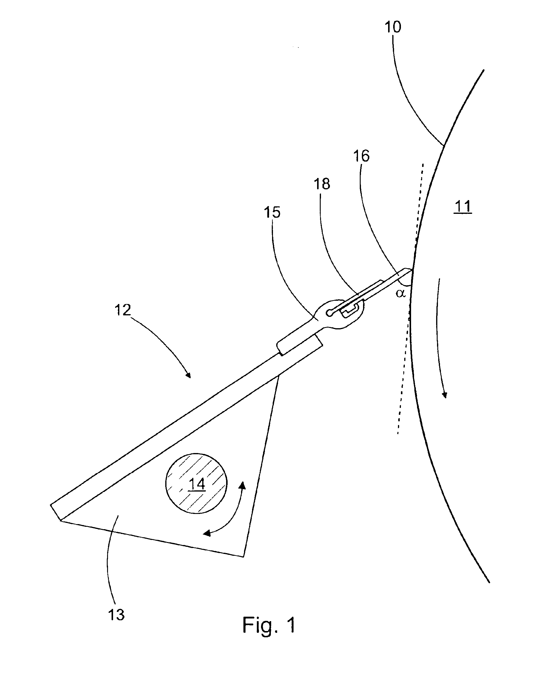
[0031]FIG. 1 shows the treatment equipment according to the invention, arranged in connection with a moving surface 10. In this case, the moving surface is a roll 11 of a paper machine, of which only a small part is shown. Generally, the treatment equipment is intended to treat a moving surface. In the doctor example, doctoring is used to remove impurities from the surface, or, for example in some positions in a paper machine, to remove the web itself. In paper, board, and other web-forming machines, the moving surfaces are also the surfaces of various cylinders and fabrics. The treatment equipment can also be used, for example, in web coating, in which a coating paste is applied to the surface of the moving web. This is shown in FIG. 6a. Further, the treatment equipment includes a frame 12, which is arranged in the vicinity of the surface 10 being treated. In FIG. 1, the frame 12 is a beam 13, which is supported rotatably on a shaft 14, from the structure of the paper machine. In p...


PUM


Abstract

A treatment equipment, which is intended to be installed in connection with a moving surface. The treatment equipment includes a frame and a blade holder formed from composite material as a single piece and connected to the frame. In addition, a blade is fitted to the blade holder, the bevelled edge belonging to which is arranged to be brought into contact with the moving surface by moving the blade holder. In the blade holder, there is also a separate backing blade, which is fitted at one edge into the blade holder, the other edge extending closer than the blade holder to the said bevelled edge.

Description

CROSS REFERENCE TO RELATED APPLICATION[0001]This application is a continuation-in-part of application Ser. No. 10 / 369,897 filed Feb. 20, 2003 now abandoned.FIELD OF THE INVENTION[0002]The present invention relates to treatment equipment, which is intended to be installed in connection with a moving surface, and which treatment equipment includes[0003]a frame, which is arranged in the vicinity of the said surface,[0004]a blade holder, which is connected to the frame,[0005]a blade fitted to the blade holder, the bevelled edge of which blade is arranged to be brought into contact with the moving surface by moving the blade holder, and[0006]a separate backing blade, which is fitted at one edge into the blade holder, the other edge extending closer than the blade holder to the said bevelled edge.BACKGROUND OF THE INVENTION[0007]The treatment equipment according to the invention is used particularly in paper machines and in other web-forming machines. In present treatment equipment, the b...

Claims


Application Information

Patent Timeline
Patent Type & Authority Patents(United States)
IPC IPC(8): B05C11/04B05C11/02D21G3/00
CPCB05C11/041B05C11/044B05C11/045D21G3/005
Inventor RATA, IIKKAHASSINEN, REIJO
Owner VALMET TECH INC
Why Eureka
Try Eureka