Ring generator for a wind power installation

a generator and ring technology, applied in the direction of motors, electrical devices, control systems, etc., can solve the problems of increased copper losses in the stator winding, high cost of reactive power or overcompensation of the stator with capacitors, and low frequency, so as to improve the efficiency of direct-driven generators

Inactive Publication Date: 2005-09-13
WOBBEN ALOYS
View PDF18 Cites 23 Cited by
  • Summary
  • Abstract
  • Description
  • Claims
  • Application Information

AI Technical Summary

Benefits of technology

The present invention improves the efficiency of generators that are directly driven and avoids the disadvantages that previously existed.

Problems solved by technology

The technical problem addressed in this patent text is the high excitation power required for slowly rotating electrical machines used in wind power installations, especially ring generators of the type E-33, E-40, E-12, and E-66 from Enercon. The efficiency of directly driven generators for wind power should be as high as possible because they are in operation for long periods of time. However, the frequency of these generators is very low, which makes it difficult to compensate for the reactive power or overcompensate the stator with capacitors. The small capacitor current in comparison with conventional frequencies of 50 or 60 Hz causes increased copper losses in the stator winding. The patent text describes a solution to this problem using a synchronous generator with a regulatable rotating magnetic field and a comparator for detecting the output voltage and comparing it to a reference voltage.

Method used


Image

  • Ring generator for a wind power installation
  • Ring generator for a wind power installation
  • Ring generator for a wind power installation

Examples


Embodiment Construction

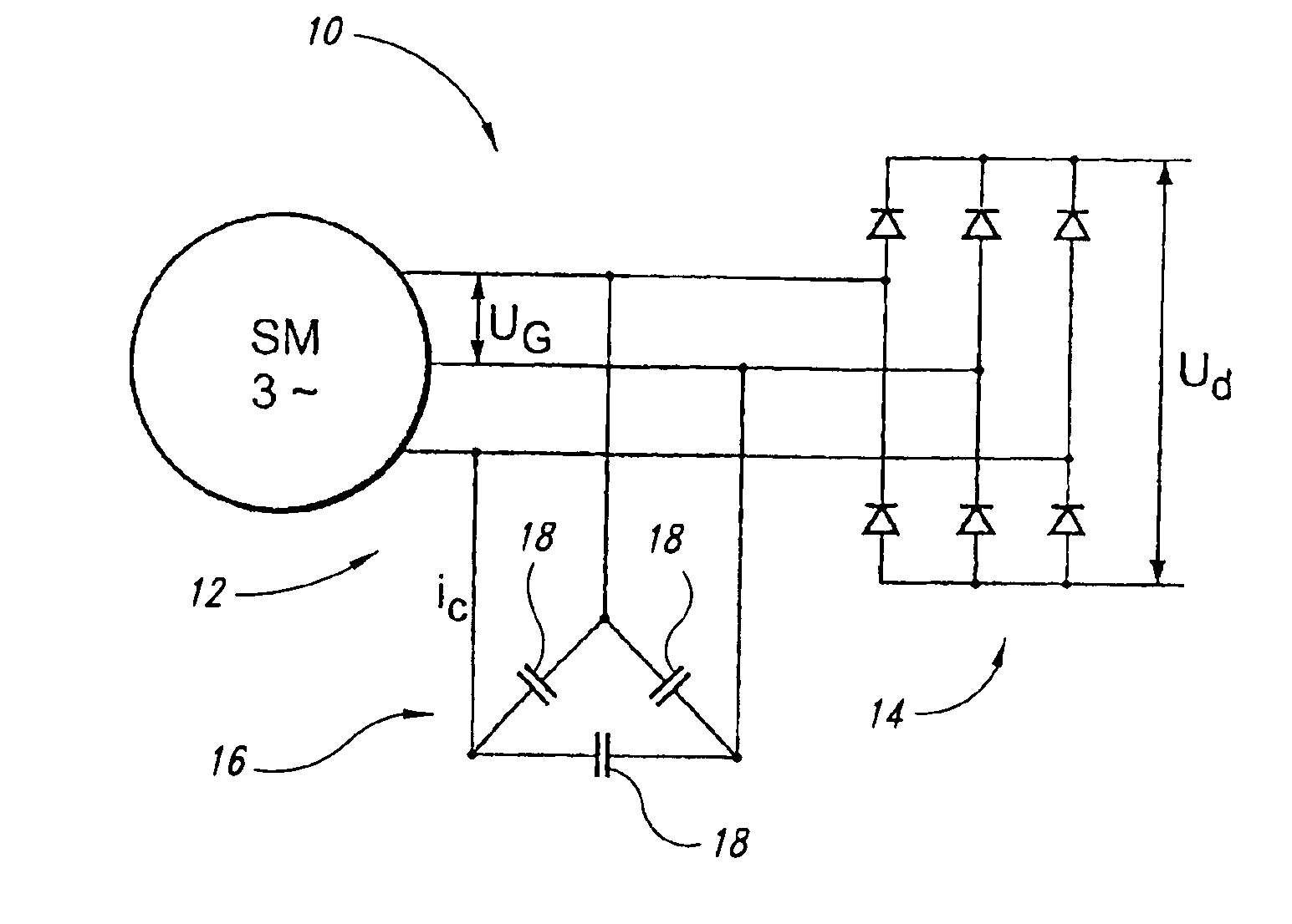
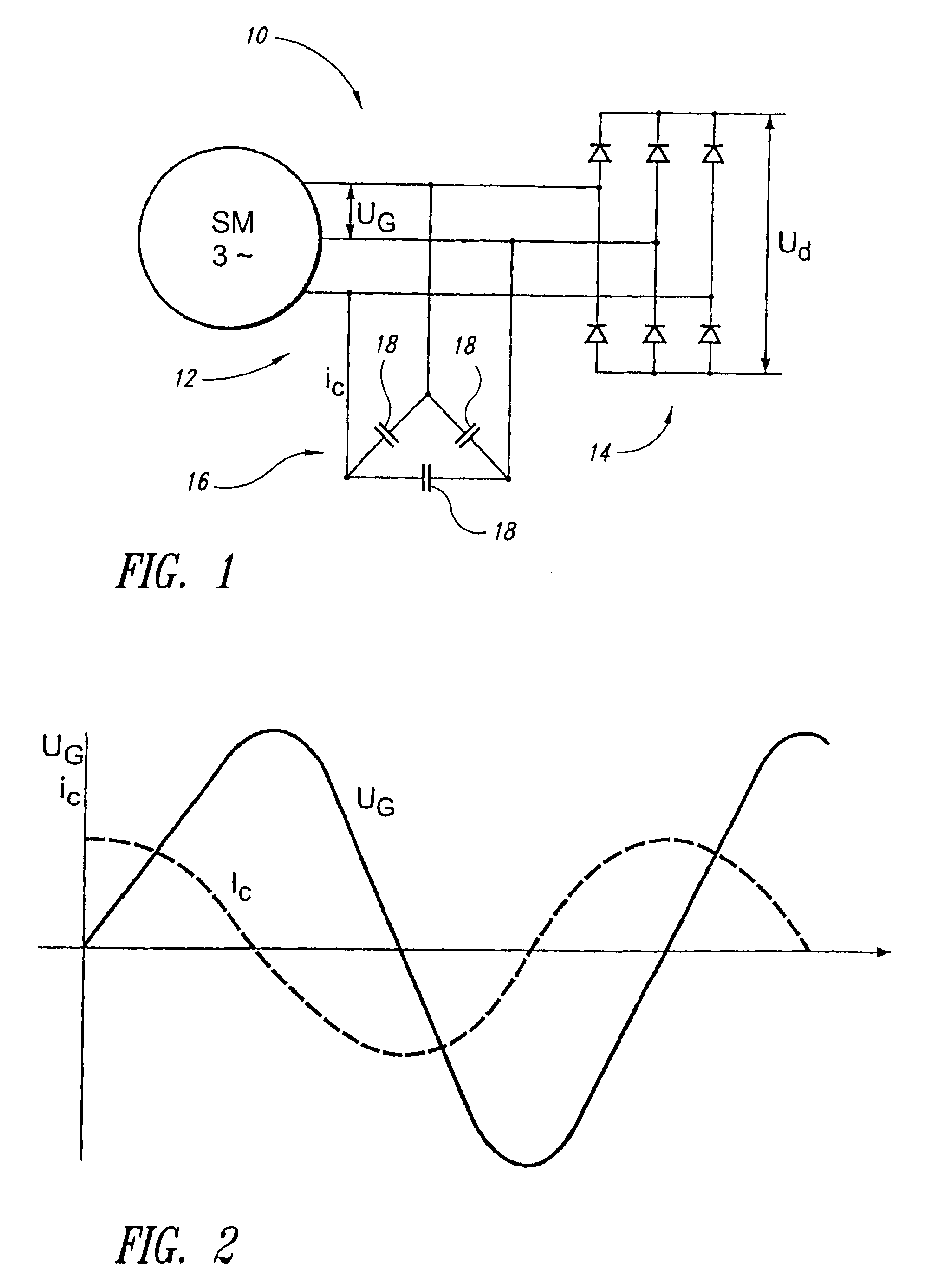
[0033]The disclosed embodiments of the present invention involve the technological approach that a part of the exciter power of the generator is applied not only by the rotor (or the winding thereof but also by the generator or the three-phase current winding thereof.

[0034]Preferably, in this case the stator is excited with a capacitive current.

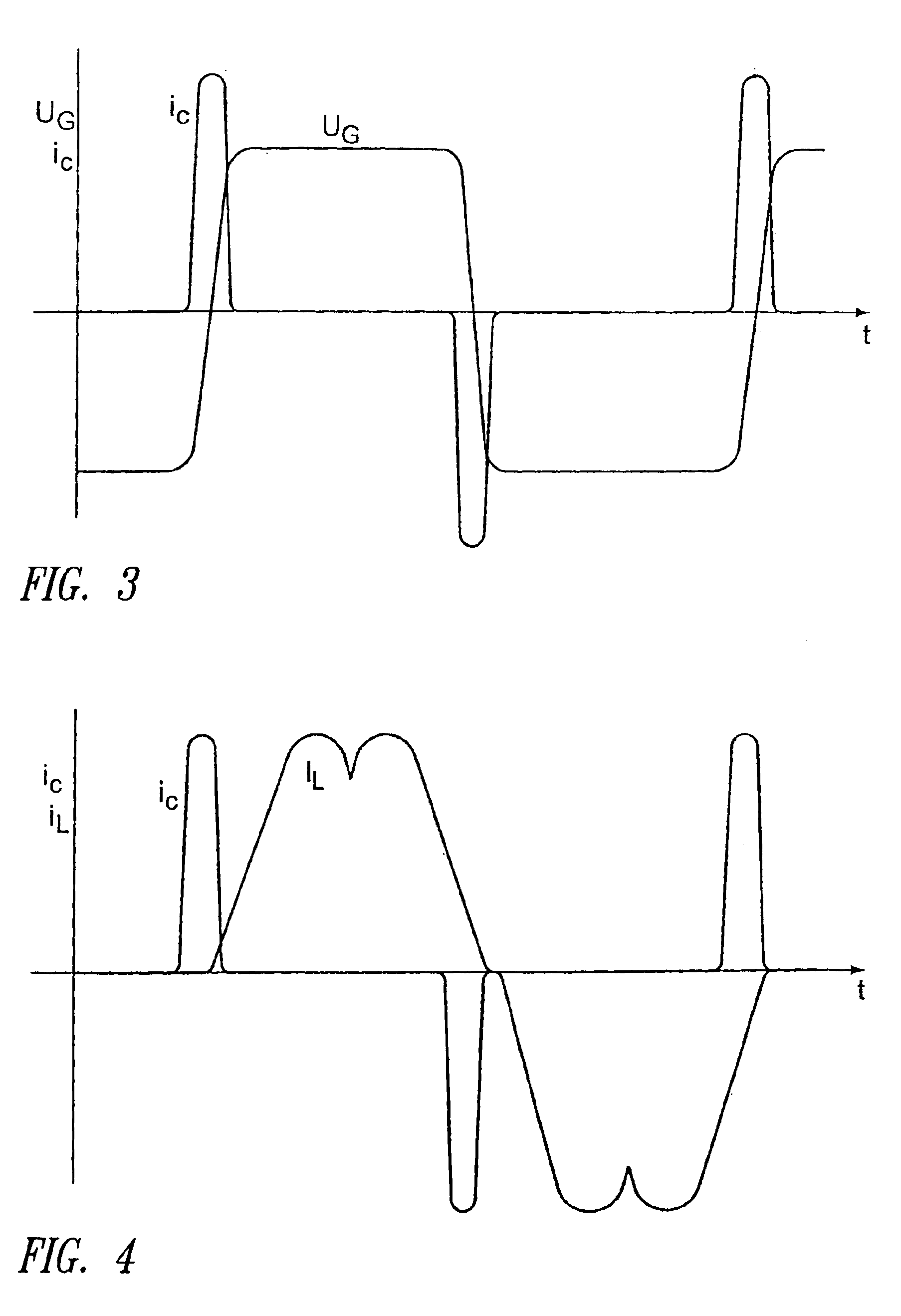
[0035]In this case the voltage induced in the stator is not sinusoidal in form but is in the nature of a trapezium, as shown in FIG. 3. Then, with the trapezoidal voltage, the capacitive capacitor current flows only during the positive or the negative edge of the voltage in accordance with the formula: ic=C·ⅆuⅆt

[0036]The current pulses which occur in that situation are of a frequency in the range of about 100 Hz and 180 Hz, and preferably 130 Hz, and affords a current amplitude that is higher approximately by a factor of 10 than when a sinusoidal voltage is involved.

[0037]A further major advantage of the generator according to the invention i...


PUM


Abstract

A slowly rotating synchronous generator (ring generator) for a wind power installation, the generator having a rotor and a stator surrounding the rotor, and the stator having at least one three-phase current winding on which a capacitive current is impressed, and the generator having a part of the exciter power of the generator produced by the stator.

Description


Claims


Application Information

Patent Timeline
Owner WOBBEN ALOYS
Why Eureka
Try Eureka