PIR motion detector for a decorative lantern

a motion detector and lantern technology, applied in the field of passive infrared motion detectors, can solve the problems of not being able to use lantern styles with the backplate-mounted motion detector, not being able to adapt to the available lantern styles, and being big and bulky

Inactive Publication Date: 2005-09-13
NINGBO UTEC ELECTRIC
View PDF13 Cites 38 Cited by
  • Summary
  • Abstract
  • Description
  • Claims
  • Application Information

AI Technical Summary

Benefits of technology

[0009]The present invention provides a motion detector in a decorative lighting fixture, the motion detector being of small size, and particularly of small transverse dimension, which permits the motion detector to be incorporated into lighting fixture designs not previously amenable to a hidden motion detector in the body of the lighting fixture. A small decorative motion detector housing is provided defining a compact interior region with a PIR sensor mounted inside and providing a sufficient optical pathway for a practical motion detector of wide angular field of view that can nevertheless fit inside commonly found small-sized decorative lantern elements. In one embodiment the motion detector is hidden in a small generally cylindrical decorative element of the sort that is found in a number of traditional decorative lantern designs and that has not previously been amenable to a hidden motion detector.

Problems solved by technology

Early passive infra-red motion detectors used for activating outdoor lighting fixtures were big and bulky.
The motion detectors of that time were contained in a separate, bulky and conspicuous housing that was unsuitable for use with stylish decorative lanterns commonly mounted in a prominent position by the front door of a house to welcome visitors.
Only a relatively few of the available lantern styles lend themselves to building in an inconspicuous motion detector.
The presence of the motion detector was nevertheless plainly evident, and some lantern styles could not be used with the backplate-mounted motion detector because a portion of the lantern necessarily extended in front of the motion detector and blocked the motion-detecting action.
While this form of design provided a decorative lantern with integrated motion detector, it could not be incorporated into most of the classic and contemporary lantern styles without interfering with the original style, if it could be incorporated at all.
Despite these developments there still exist a plethora of historic and contemporary decorative lantern styles that are not amenable to a hidden motion detector in the fixture body.
Problems arise when the motion detector is incorporated into the body of the lantern because there is limited space for the optical and electronic elements and because the interior volume available for the motion detector elements may be awkwardly shaped.
The volume of the space to work with and the shape of the decorative exterior fixture walls impose constraints on the technical design of the motion detector.
To add a motion detector to many stylistic lantern designs, it has been necessary either to add a further housing element to the lantern, adversely altering the lantern style, or to place the motion detector on the backplate.

Method used


Image

  • PIR motion detector for a decorative lantern
  • PIR motion detector for a decorative lantern
  • PIR motion detector for a decorative lantern

Examples


Embodiment Construction

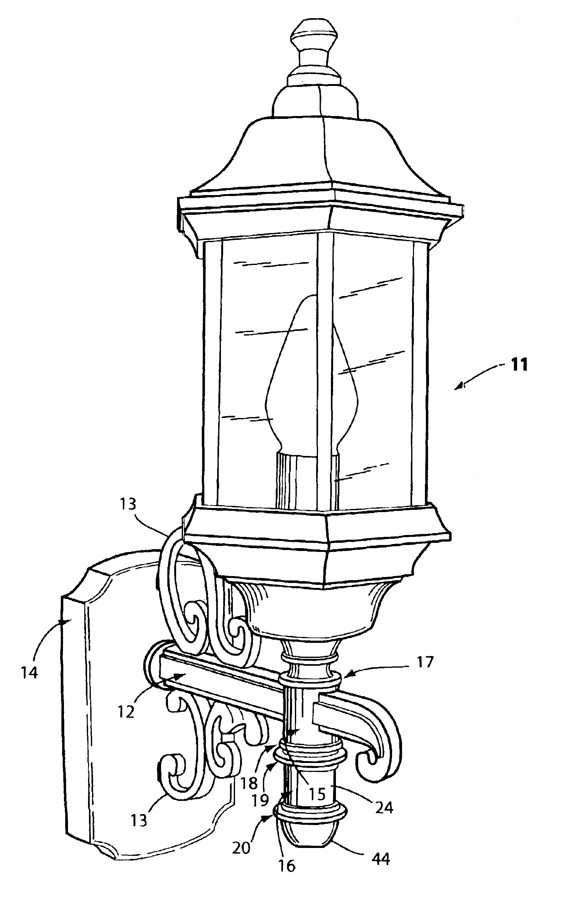
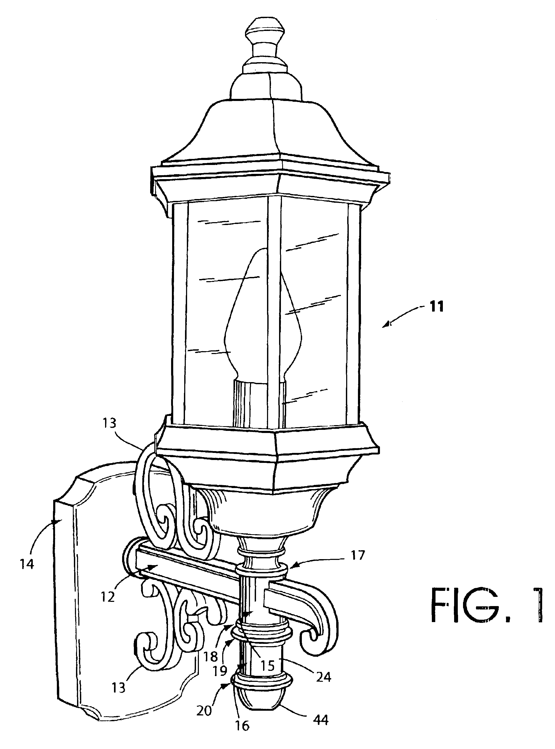
[0018]FIG. 1 shows a decorative lighting fixture including a motion detector integrated into the lighting fixture in a completely inconspicuous manner so as not to degrade the stylistic integrity of the fixture. The lighting fixture includes a decorative lantern 11, a decorative support arm 12 with decorative embellishments 13 for supporting lantern 11, and a backplate or base 14 for mounting the lighting fixture on a wall. Support arm 12 is connected to the lantern through a decorative connective element 15. The lantern also includes a decorative assembly 16, which serves here as a motion detector housing.

[0019]The decorative assembly 16 illustrated in FIG. 1 is of the form of a small cylindrical element in the same general size and style as decorative connective element 15. The decorative elements 15 and 16 have an outside diameter on the order of a little over one inch (about one and one-eighth inch. The two elements 15 and 16 are adorned with decorative rings 17-20 so as to main...


PUM


Abstract

A small-sized hidden motion detector that can be incorporated in a decorative manner into a decorative lantern. The motion detector can be incorporated into lighting fixture designs not previously amenable to a hidden motion detector in the body of the lighting fixture. A small decorative motion detector housing is provided defining a compact interior region with a PIR sensor mounted inside and providing a sufficient optical pathway for a practical motion detector of wide angular field of view that can nevertheless fit inside commonly found small-sized decorative lantern elements. In one embodiment the motion detector is hidden in a small generally cylindrical decorative element of the sort that is found in a number of traditional decorative lantern designs and that has not previously been amenable to a hidden motion detector. Another embodiment includes a mechanism for mechanically adjusting the range and responsiveness of the motion detector notwithstanding the small size of the space available for housing the detector.

Description

[0001]This application claims the benefit of provisional application No. 60 / 362,753 filed Mar. 7, 2002.BACKGROUND OF THE INVENTION[0002]The present invention relates to passive infrared motion detectors of the type used in residential outdoor lighting fixtures, for example, to illuminate a walkway or driveway when a person or automobile approaches. The invention is more particularly directed to an arrangement for making the motion detector an inconspicuous element of the lighting fixture and to an arrangement for adjusting the motion detector range.[0003]Early passive infra-red motion detectors used for activating outdoor lighting fixtures were big and bulky. They were only used with floodlights or with other non-decorative, primarily utilitarian lighting. The motion detectors of that time were contained in a separate, bulky and conspicuous housing that was unsuitable for use with stylish decorative lanterns commonly mounted in a prominent position by the front door of a house to we...

Claims


Application Information

Patent Timeline
Patent Type & Authority Patents(United States)
IPC IPC(8): G08B13/19G08B13/189
CPCG08B13/19Y10S362/802
Inventor LEE, WADESANDELL, DONALD R.
Owner NINGBO UTEC ELECTRIC
Why Eureka
Try Eureka