Bottoming sensor

a sensor and bottoming technology, applied in the field of bottoming sensors, can solve the problems of bed sores and other complications, adversely affecting other medical equipment, and affecting the well-being of patients,

Active Publication Date: 2005-09-13
STRYKER CORP
View PDF8 Cites 59 Cited by
  • Summary
  • Abstract
  • Description
  • Claims
  • Application Information

AI Technical Summary

Problems solved by technology

It is known that interface pressures can significantly affect the well-being of immobile patients in that higher interface pressures can reduce local blood circulation, tending to cause bed sores and other complications.
Those signal devices generate electrical signals, like rf signals, that may, however, adversely effect other medical equipment.
The system of the '289 patent does have some potential problems.
One of those problems is that the transmission of the electrical signal may interfere with medical devices.
Prior to bottoming occurring, the pressure exerted by the bladder on the skin of the object becomes excessive.

Method used


Image

  • Bottoming sensor
  • Bottoming sensor
  • Bottoming sensor

Examples


Embodiment Construction

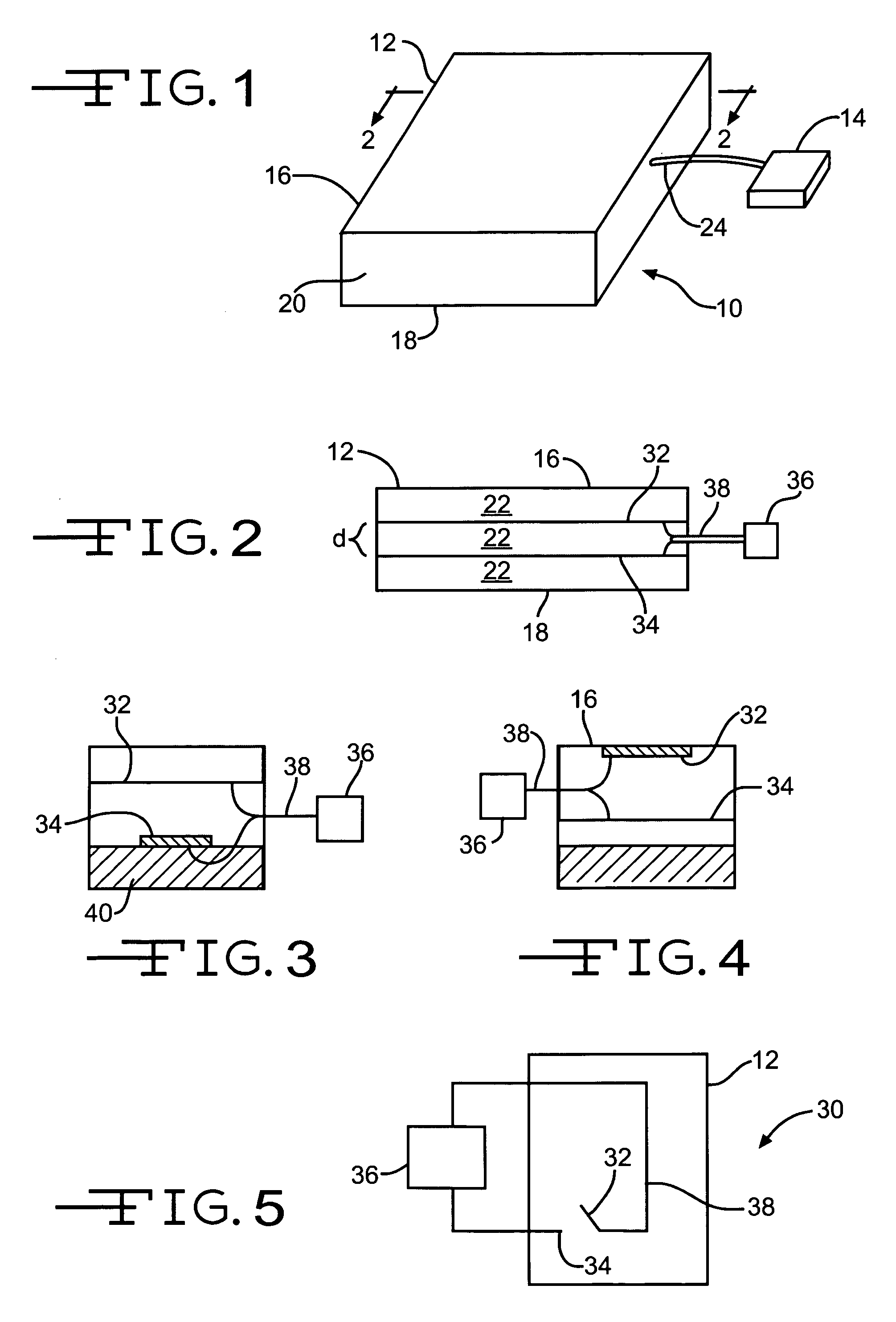
[0027]The present invention as shown in FIG. 1 has at least one inflatable cushion 10 having at least one bladder 12. The bladder 12, in at least one embodiment of the present invention, is interconnected to a pump 14 as shown in FIG. 1. The pump 14 provides a fluid to the bladder 12. The fluid can be a gas or a liquid. If a gas is used, the preferred gas is air. And if a liquid is used, the preferred liquid is an aqueous solution, preferably non-ionic.

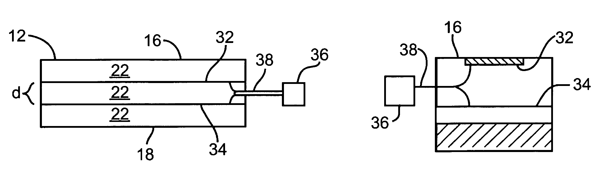
[0028]The bladder 12 can be made of polymeric materials having a top surface 16 capable of receiving an object, a bottom surface 18 that is opposite the top surface, and at least one side 20 positioned between the top and the bottom surfaces. The top surface 16, the bottom surface 18, and the at least one side 20 define the perimeter of a bladder cavity 22, as illustrated in FIG. 2. The bladder cavity is designed to contain the fluid.

[0029]Every inflatable bladder is capable of receiving through an inlet 24 a fluid from a fluid source...


PUM


Abstract

The present invention is directed to a cushioning device. The present cushioning device has many attributes that are common with many cushions. Some of these common attributes are at least one bladder having a top surface, a bottom surface and at least one side surface positioned between the top and the bottom surfaces. Another common attribute is a bladder cavity being defined by the top surface, the bottom surface and the at least one side surface. The present invention differs from other bladders in that there is a first conductive material and a second conductive material are positioned within the bladder cavity, positioned away from the bottom surface of the bladder, and capable of acting like a switch for a reactive device. The reactive device is electrically interconnected with the first and second conductive materials. When the first and second conductive materials contact each other the reactive device is capable of responding by sounding an alarm and/or re-inflating the bladder cavity with a fluid.

Description

CLAIM OF PRIORITY[0001]This application claims priority to U.S. provisional patent application Ser. No. 60 / 392,509 which was filed on Jun. 27, 2002.FIELD OF THE INVENTION[0002]The present invention relates to a device for sensing and monitoring the position of a patient upon a cushion and for controlling the inflation volume of the cushion.BACKGROUND OF THE INVENTION[0003]Gaymar Industries, Inc., the assignee of this application, is a manufacturer of cushion like devices. These cushions which have at least one bladder are designed to contain fluids. In many cases the fluid is water and / or air. These cushions are used as seat cushions, mattresses, overlays and any other cushion designed to have a patient positioned thereon. Most of the cushions made by Gaymar are designed for therapeutic purposes.[0004]Inflatable therapeutic cushions for patients have been known for many years. Many therapeutic cushions are designed to reduce “interface pressures”; the pressure encountered between a ...

Claims


Application Information

Patent Timeline
Patent Type & Authority Patents(United States)
IPC IPC(8): A47C27/08A47C27/10G08B21/00A47C27/00A61G7/05A61G7/057
CPCA47C27/082A47C27/083A47C31/123A47C31/126A61G7/05769Y10S5/94
Inventor ELLIS, JOHN
Owner STRYKER CORP
Why Eureka
Try Eureka