A piezo-driven infusion set

A piezoelectric drive, infusion set technology, applied in the field of medical devices, can solve problems such as aggravating the burden on the heart, blood backflow, and large differences in blood drug concentration, and achieve the effect of convenient movement and portability, and improved gas pressure.

Active Publication Date: 2021-02-19
ZHEJIANG NORMAL UNIVERSITY
View PDF11 Cites 0 Cited by
  • Summary
  • Abstract
  • Description
  • Claims
  • Application Information

AI Technical Summary

Problems solved by technology

This infusion mode will bring many problems in actual use: the flow rate is adjusted manually, and the flow control accuracy is not enough; the infusion bottle needs to be held high by others when the patient walks or goes to the toilet, which is inconvenient to move and the height of the infusion bottle is not high enough. Make the blood flow back; patients or nurses need to be guarded for a long time, if the infusion is not found in time, it may cause accidents; the liquid medicine is in contact with the air, and the ambient air may be polluted when the air is unclean
In addition to the above direct problems, sometimes the infusion time is shortened by reducing the amount of solution, speeding up the infusion speed, etc., which not only increases the burden on the heart, but also affects the therapeutic effect: intramuscular injection and subcutaneous injection in a relatively short period of time. The biggest disadvantage of injecting into muscle or subcutaneous is that the blood drug concentration varies greatly within an injection cycle, which is not conducive to the effective absorption and utilization of drugs, because most drugs have a better concentration range in the human body, and when the drug concentration is too high Has toxic side effects, if it is too low, it will have no therapeutic effect

Method used


Image

  • A piezo-driven infusion set
  • A piezo-driven infusion set
  • A piezo-driven infusion set

Examples


Embodiment Construction

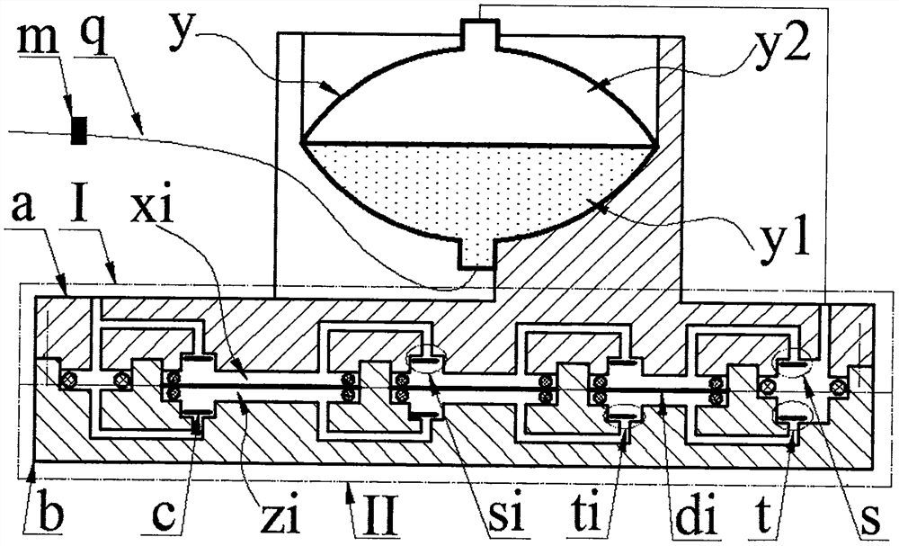
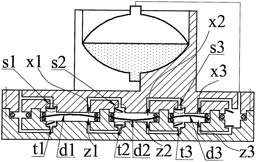
[0014] The top of the seat plate a0 of the main body a is provided with a cavity a9, and the cavity a9 is equipped with a medicine bag y composed of a medicine cavity y1 and an air cavity y2; the bottom of the seat plate a0 is provided with a left boss a1, a right boss a2 and at least two A body platform a3i whose diameter decreases successively from left to right, the upper inlet hole a4 is arranged on the left boss a1, the upper outlet cavity a5 and the upper outlet hole a8 are arranged on the right boss a2, and the upper inlet hole a4 is arranged on the body platform a3i. The mouth a6 and the upper air outlet a7; the upper inlet a6 of the leftmost body platform a3i communicates with the upper inlet a4, the upper air outlet a7 of the rightmost body platform a3i communicates with the upper outlet a5, and the other two adjacent body platforms The upper inlet a6 and the upper air outlet a7 of a3i communicate with each other; the upper inlet a6 and the upper outlet a5 and the val...


PUM


Abstract

The invention relates to a piezoelectric-driven transfusion device, which belongs to the field of medical equipment. The seat plate of the main body is provided with a cavity, and a medicine bag with a medicine cavity and an air cavity is installed in the cavity; the bottom of the seat plate is provided with left and right bosses and at least two body platforms whose diameters decrease successively from left to right, and on the left boss There is an upper inlet hole, an upper outlet cavity and an upper outlet hole are arranged on the right boss, an upper inlet cavity and an upper air outlet are arranged on the body platform; left and right cavities and body cavities equal in number and diameter to the body platform are respectively arranged on the base, The bottom wall of the left cavity is provided with a lower inlet hole, the bottom wall of the right cavity is provided with a lower outlet cavity, and the bottom wall of the body cavity is provided with a lower inlet cavity and a lower air outlet; The plate is mounted on the base and the upper and lower inlet holes are connected, the upper and lower outlet openings are connected with the upper outlet hole, the body platform presses the piezoelectric driver in the body cavity through the sealing ring to form the upper and lower compression chambers, and the upper and lower compression chambers connected in series are connected in parallel; the air chamber It communicates with the upper outlet hole through the air pipe, and the infusion pipe of the medicine cavity is equipped with a flow valve and a needle.

Description

technical field [0001] The invention belongs to the field of medical equipment, and in particular relates to a piezoelectric-driven infusion set. Background technique [0002] Existing injections mainly include intravenous injection, intramuscular injection and subcutaneous injection. Intravenous injection is also called infusion drug administration. Most of the existing infusion devices are composed of infusion bottles, infusion tubes and infusion stands. This infusion mode will bring many problems in actual use: the flow rate is adjusted manually, and the flow control accuracy is not enough; the infusion bottle needs to be held high by others when the patient walks or goes to the toilet, which is inconvenient to move and the height of the infusion bottle is not high enough. Make the blood flow back; the patient or the nursing staff need to watch for a long time, if the infusion is not found in time, it may cause an accident; the liquid medicine is in contact with the air,...

Claims


Application Information

Patent Timeline
Patent Type & Authority Patents(China)
IPC IPC(8): A61M5/155A61M5/168
Inventor 王淑云杨泽盟廖泳万嫩柴超辉程光明
Owner ZHEJIANG NORMAL UNIVERSITY
Why Eureka
Try Eureka