Gaze tracking system, eye-tracking assembly and an associated method of calibration

Inactive Publication Date: 2005-09-13
THE BOEING CO
View PDF20 Cites 207 Cited by
  • Summary
  • Abstract
  • Description
  • Claims
  • Application Information

AI Technical Summary

Benefits of technology

[0010]In light of the foregoing background, the present invention therefore provides an improved eye-tracking assembly, gaze tracking system and method of calibration. According to the present invention, the eye-tracking assembly includes a visor that, at least a portion of which, is capable of being located outside the central field of view of the operator. As such, the operator

Problems solved by technology

Whereas conventional head/eye tracking devices are adequate in tracking the head and eye position of the operator, such conventional tracking devices have drawbacks.
In this regard, the mirror is an unnatural obstruction in the operator's visual field of view, limiting the operator's feeling of visual immersion in a virtual reality application, such as that found in flight simulation systems.
In addition to the structural drawback of the partially reflective/partially transmissive flat mirror 18, the method by

Method used


Image

  • Gaze tracking system, eye-tracking assembly and an associated method of calibration
  • Gaze tracking system, eye-tracking assembly and an associated method of calibration
  • Gaze tracking system, eye-tracking assembly and an associated method of calibration

Examples


Embodiment Construction

[0023]The present invention now will be described more fully hereinafter with reference to the accompanying drawings, in which preferred embodiments of the invention are shown. This invention may, however, be embodied in many different forms and should not be construed as limited to the embodiments set forth herein; rather, these embodiments are provided so that this disclosure will be thorough and complete, and will fully convey the scope of the invention to those skilled in the art. Like numbers refer to like elements throughout.

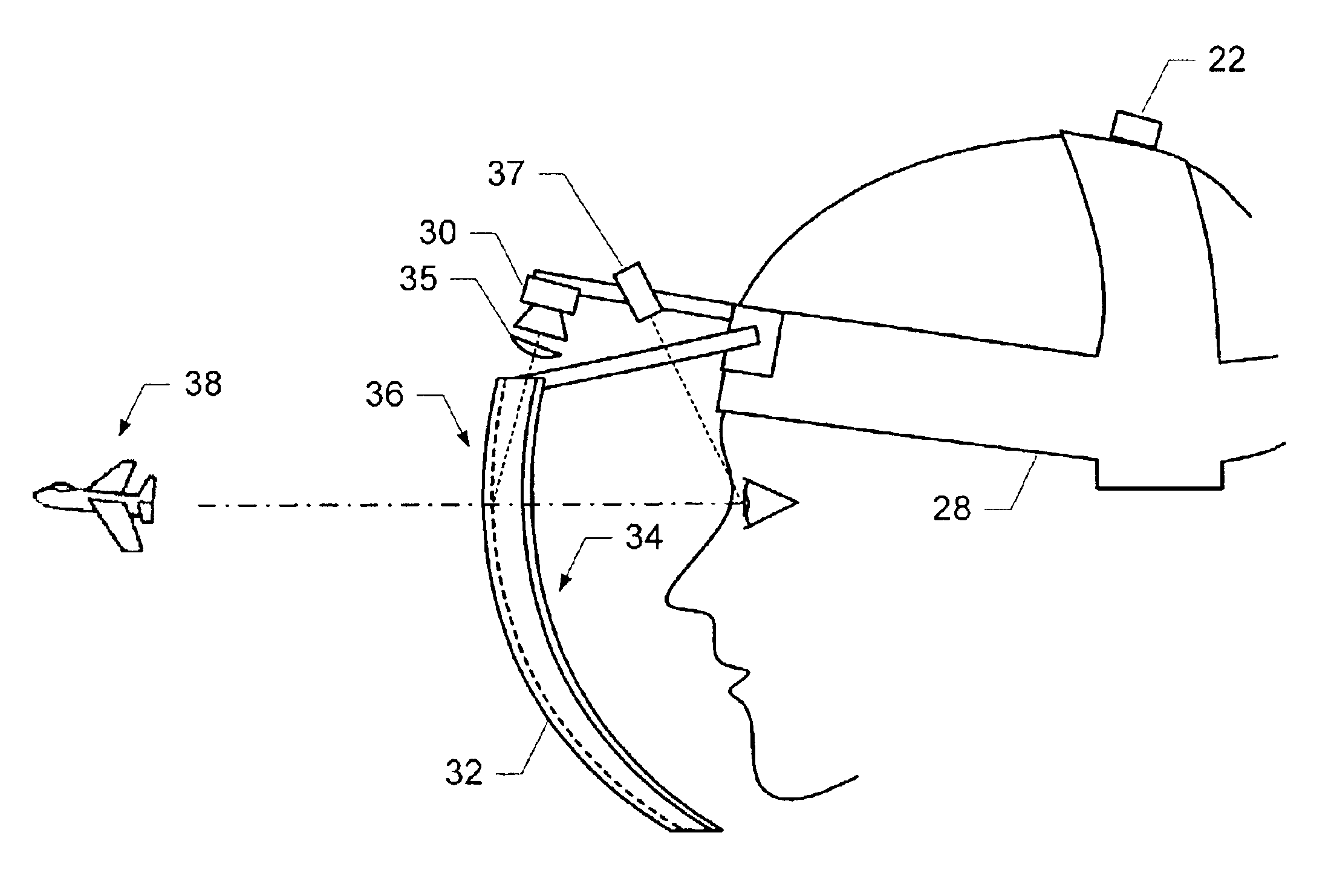
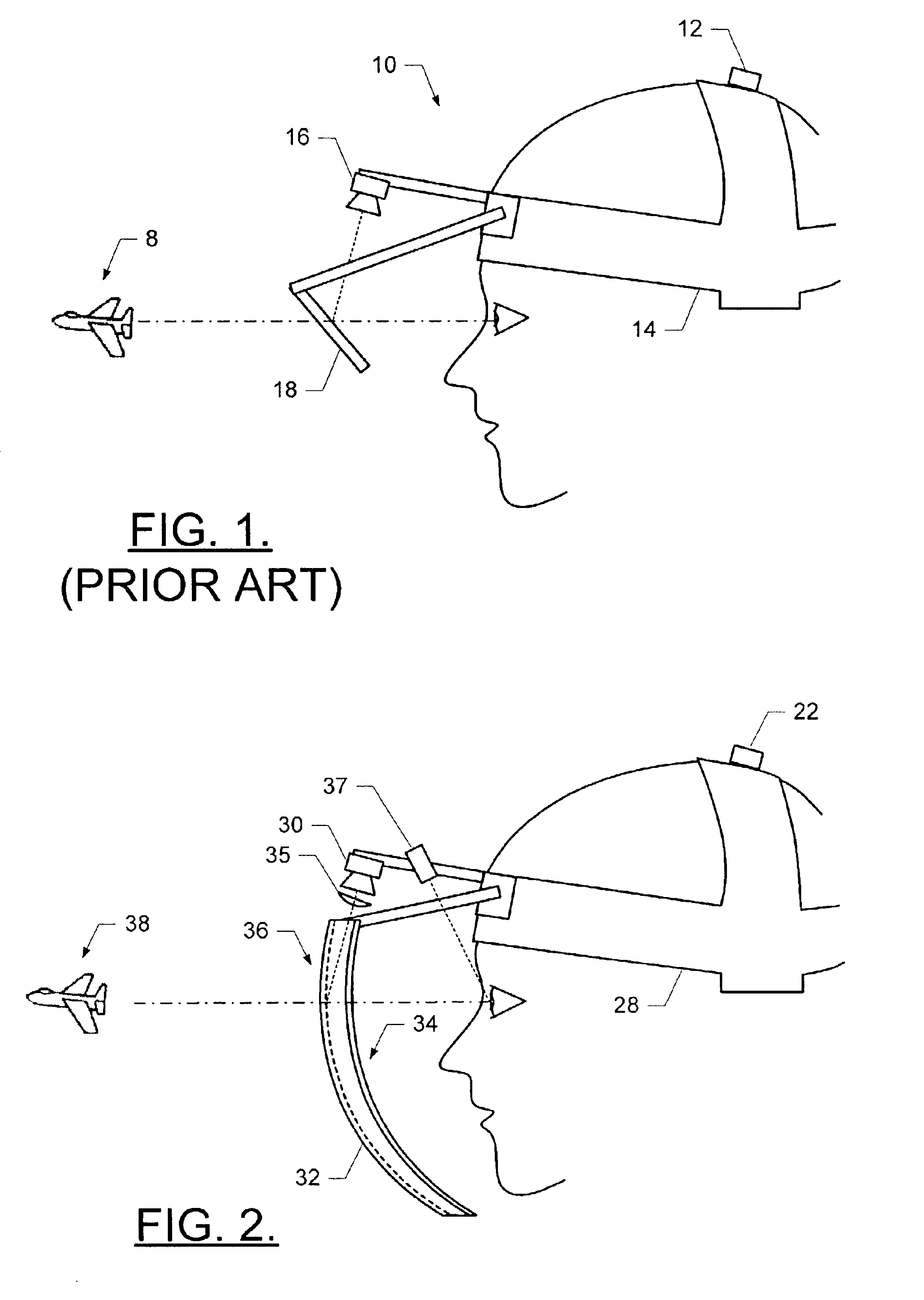
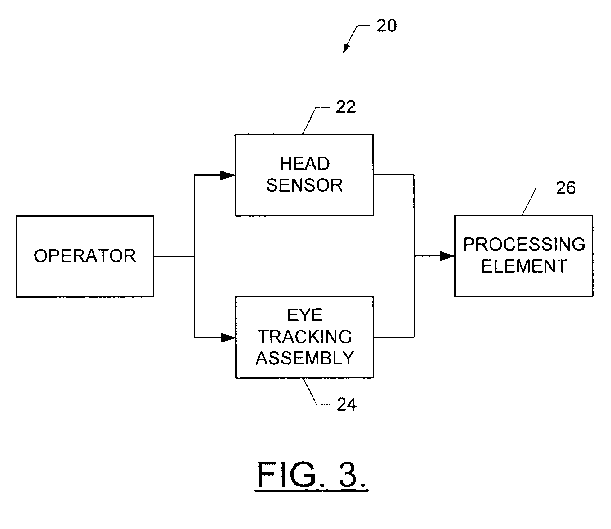
[0024]Referring to FIGS. 2 and 3, a gaze tracking system 20 according to one embodiment of the present invention is shown. The system includes a head-mounted head tracking sensor 22, a head-mounted eye tracking assembly 24, and a processing element 26. The head tracking sensor and eye tracking assembly are mounted to an operator's head by means of a headband 28, helmet or other head-mounted securing device. The head tracking sensor is mounted to the operat...


PUM


Abstract

A system for tracking a gaze of an operator includes a head-mounted eye tracking assembly, a head-mounted head tracking assembly and a processing element. The head-mounted eye tracking assembly comprises a visor having an arcuate shape including a concave surface and an opposed convex surface. The visor is capable of being disposed such that at least a portion of the visor is located outside a field of view of the operator. The head-mounted head tracking sensor is capable of repeatedly determining a position of the head to thereby track movement of the head. In this regard, each position of the head is associated with a position of the at least one eye. Thus, the processing element can repeatedly determine the gaze of the operator, based upon each position of the head and the associated position of the eyes, thereby tracking the gaze of the operator.

Description

FIELD OF THE INVENTION[0001]The present invention relates generally to head / eye tracking systems for visual display systems and, more particularly, to head / eye tracking systems including an eye tracking device having a curved visor.BACKGROUND OF THE INVENTION[0002]Visual display systems, such as flight simulation systems, are commonly employed to train military and commercial pilots. Conventional visual display systems include one or more screens onto which a video image is projected by one or more projectors containing image sources, such as cathode ray tubes (CRTs). The operator of the visual display system is also generally provided with a control panel and, in some instances, a joystick for providing input to the visual display system in response to the displayed video image. In this regard, the control panel and joystick are often designed to duplicate the controls and displays found in an aircraft. Thus, the operator can simulate the flight of an aircraft, for example, and can...

Claims


Application Information

Patent Timeline
IPC IPC(8): A61B3/113G02B27/01G06F3/00G02B27/00G06F3/01
CPCA61B3/113G02B27/017G06F3/013G02B2027/0138G02B2027/014G02B2027/0187G02B2027/0198G06V40/19
Inventor AUGHEY, JOHN H.ROHR, MICHAEL V.SWAINE, STEVEN D.VORST, CARL J.
Owner THE BOEING CO
Why Eureka
Try Eureka