
Method and device for producing height images of technical surfaces with microscopic resolution

a technology of microscopic resolution and height image, which is applied in the field of height image of technical surfaces with microscopic resolution, can solve the problems of inability to detect local areas with highly varying degrees simultaneously, time-consuming method, and various drawbacks of said known method

Inactive Publication Date: 2005-09-13
NANOFOCUS
View PDF6 Cites 6 Cited by
  • Summary
  • Abstract
  • Description
  • Claims
  • Application Information

AI Technical Summary

Benefits of technology

[0023]Owing to the fact that the sample is displaced in a continuous movement, a completely jerk-free location-dependent image recording is obtained in addition to the advantage gained in terms of time. The individual images are stored in this connection in a form meeting the evaluation requirements. This means that with a total number of N images, whose digitization is triggered in the course of the measurement, a number N of successive storage locations are occupied for every pixel. Said storage locations are now successively filled from the first to the last image. The advantage of this is that the intensities of a pixel required for the later calculation are arranged in the technically useful sequence. The sequence permitting quick access to the measured data is defined as being the technically useful sequence.

Problems solved by technology

However, said known method is afflicted with various drawbacks.
The low dynamics of a CCD-camera leads to the fact that local areas reflecting to highly varying degrees cannot be detected simultaneously.
The method is rather time-consuming because of the additional run-through needed for the determination of the threshold (see above).
Furthermore, the time expenditure is increased by the step-by-step adjustment of the displacement.
Moreover, this may cause shocks notably as the mechanical system is being accelerated and slowed down.
Another drawback arises from the accumulative evaluation addressed above.
The evaluation according to the above formula fails when several maximums appear, or it supplies erroneous values.
The possibility of detecting evaluation errors and the determination of the quality of the measurement are generally inadequate, to begin with.
An additional drawback has to be seen in that the displacement unit has to be controlled by the controller because no direct coupling is available between the displacement unit and the unit digitizing the image.

Method used


Image

  • Method and device for producing height images of technical surfaces with microscopic resolution
  • Method and device for producing height images of technical surfaces with microscopic resolution
  • Method and device for producing height images of technical surfaces with microscopic resolution

Examples


Embodiment Construction

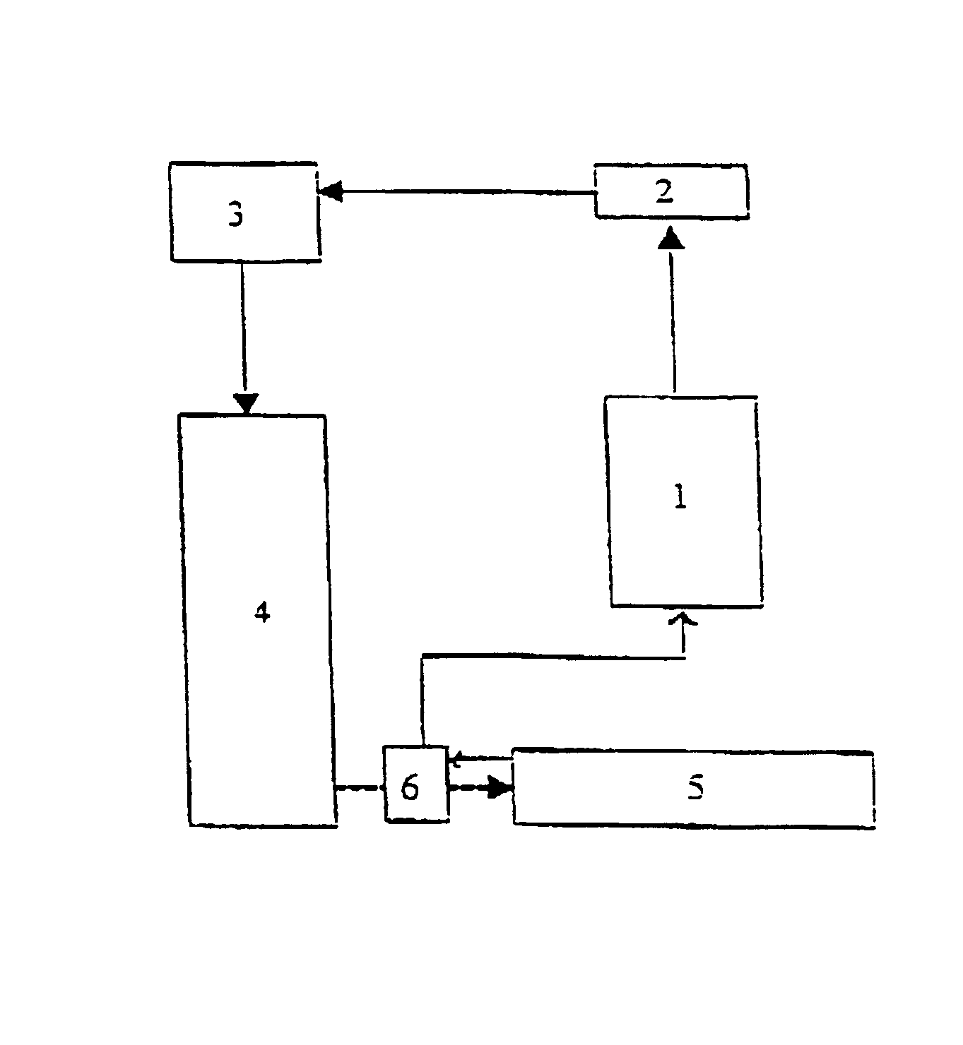
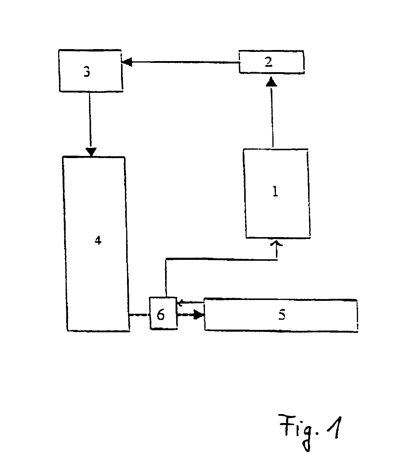
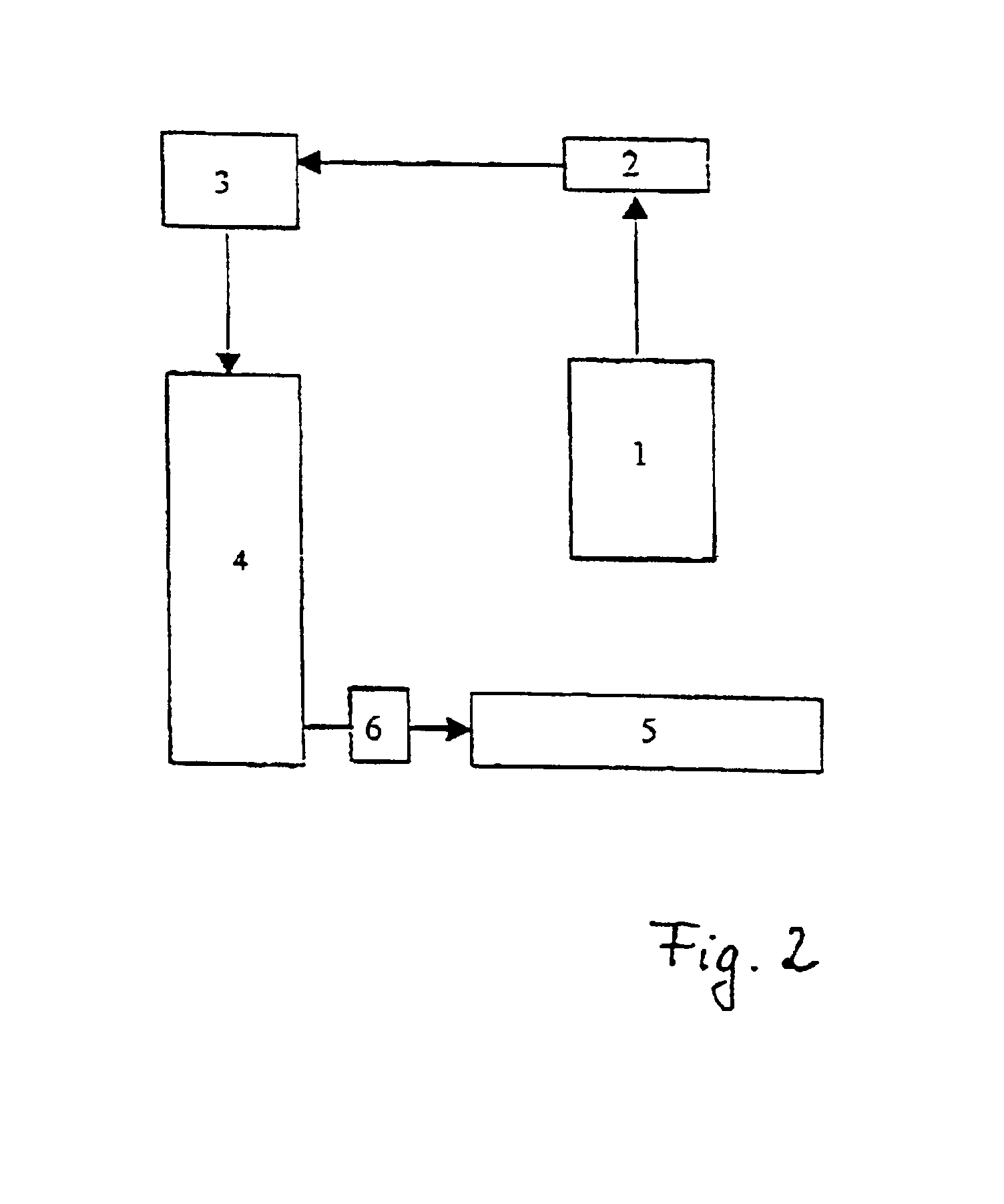
[0046]In both figures, identical elements are denoted by the same reference numerals. Both circuit diagrams have in common the confocal optical microscope branch denoted by the reference numeral 1, whose images are recorded by a digital camera 2, by which the images are then transmitted in the digitized form to a system controller 4 via a digitizing unit 3. The recorded images are then evaluated in said system controller. The sample to be measured is located on a motor-driven displacement unit 5 for through-focusing the surface of the sample. The displacement movement in the direction of the microscope 1 is effected by the controller 4 via the control 6 (FIG. 2).

[0047]The device according to FIG. 2, that is to say the device as defined by the invention, is different in that a location detection system is arranged on the displacement unit 5. Such location detection system may be, for example an incremental decoder mounted on the axis of the motor employed for the displacement, or an ...


PUM


Abstract

A method for producing height images of technical surfaces with microscopic resolution uses a confocal measuring microspace. The sample to be measured is displaced in the direction (Z direction) towards the microspace in a controlled manner and images are produced at defined distances with a digital camera. The digitized images recorded are transmitted to a controller (PC) for further processing and evaluation and the light intensity maximum for every pixel is detected, the position of the maximum indicating the height of the sample to be measured. The sample is displaced in a continuous manner and that the image exposures are triggered at discrete localized distances. The intensities of the N individual images recorded and digitized in the above manner are stored in the PC in such a manner that a number N of subsequent storage locations is occupied for every pixel.

Description

CROSS REFERENCE TO RELATED APPLICATIONS[0001]Applicants claim priority under 35 U.S.C. §119 of German Application No. 100 05 852.3, filed on Feb. 10, 2000. Applicants also claim priority under 35 U.S.C. 365 of PCT / DE01 / 00086, filed on Jan. 11, 2001. The international application under PCT article 21 (2) was not published in English.BACKGROUND OF THE INVENTION[0002]1. Field of the Invention[0003]The invention relates to a method and a device for producing height images of technical surfaces with microscopic resolution with the help of a confocal measuring microscope, whereby the sample to be measured is displaced in a controlled manner in the direction (Z-direction) of the microscope and images are produced at defined distances by means of a digital camera, and the recorded digitized images are transmitted to a controller (PC) for further processing and evaluation, in a manner such that the light intensity maximum is detected for each pixel and the position of the maximum indicates t...

Claims


Application Information

Patent Timeline
Patent Type & Authority Patents(United States)
IPC IPC(8): G02B21/00G01B11/24
CPCG02B21/0024G02B21/008
Inventor VALENTIN, JURGENJORDAN, JOACHIMSCHREIER, HANS-HERMANN
Owner NANOFOCUS
Learn More