Single cell liquid crystal shutter glasses

Inactive Publication Date: 2005-09-13
REVEO
View PDF16 Cites 49 Cited by
  • Summary
  • Abstract
  • Description
  • Claims
  • Application Information

AI Technical Summary

Benefits of technology

[0006]The invention is a stereoscopic shutter system having a single liquid crystal (LC) cell. The system may have flexible substrates or non-flexible substrates. The system requires only two electrical conductors to shutter both eyes. The system uses twisted nematic liquid crystal, ferro-electric liquid crystal, pi-cell t

Problems solved by technology

Further, current systems use LC cells that are constructed from glass substrates

Method used


Image

  • Single cell liquid crystal shutter glasses
  • Single cell liquid crystal shutter glasses
  • Single cell liquid crystal shutter glasses

Examples


Embodiment Construction

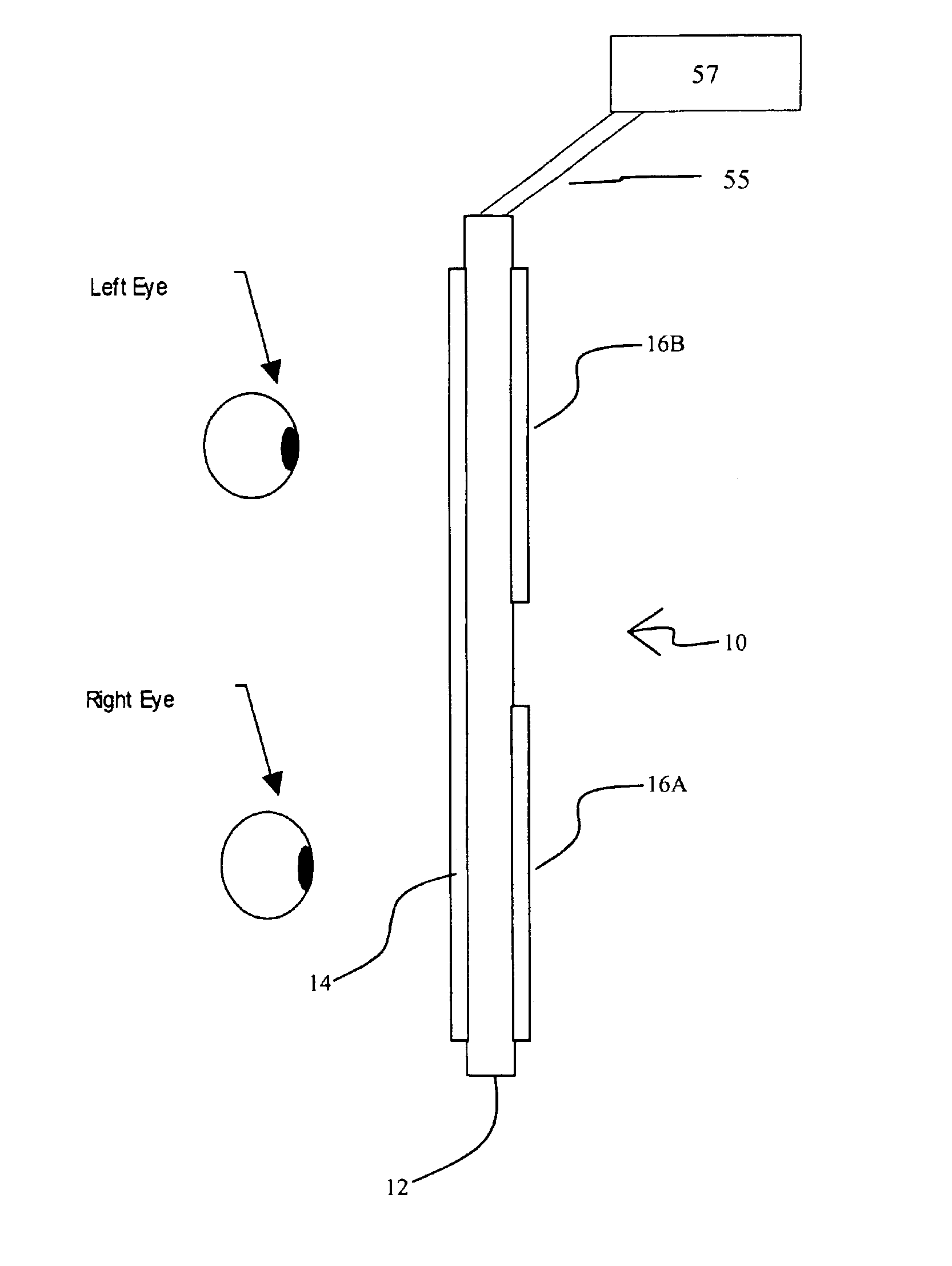
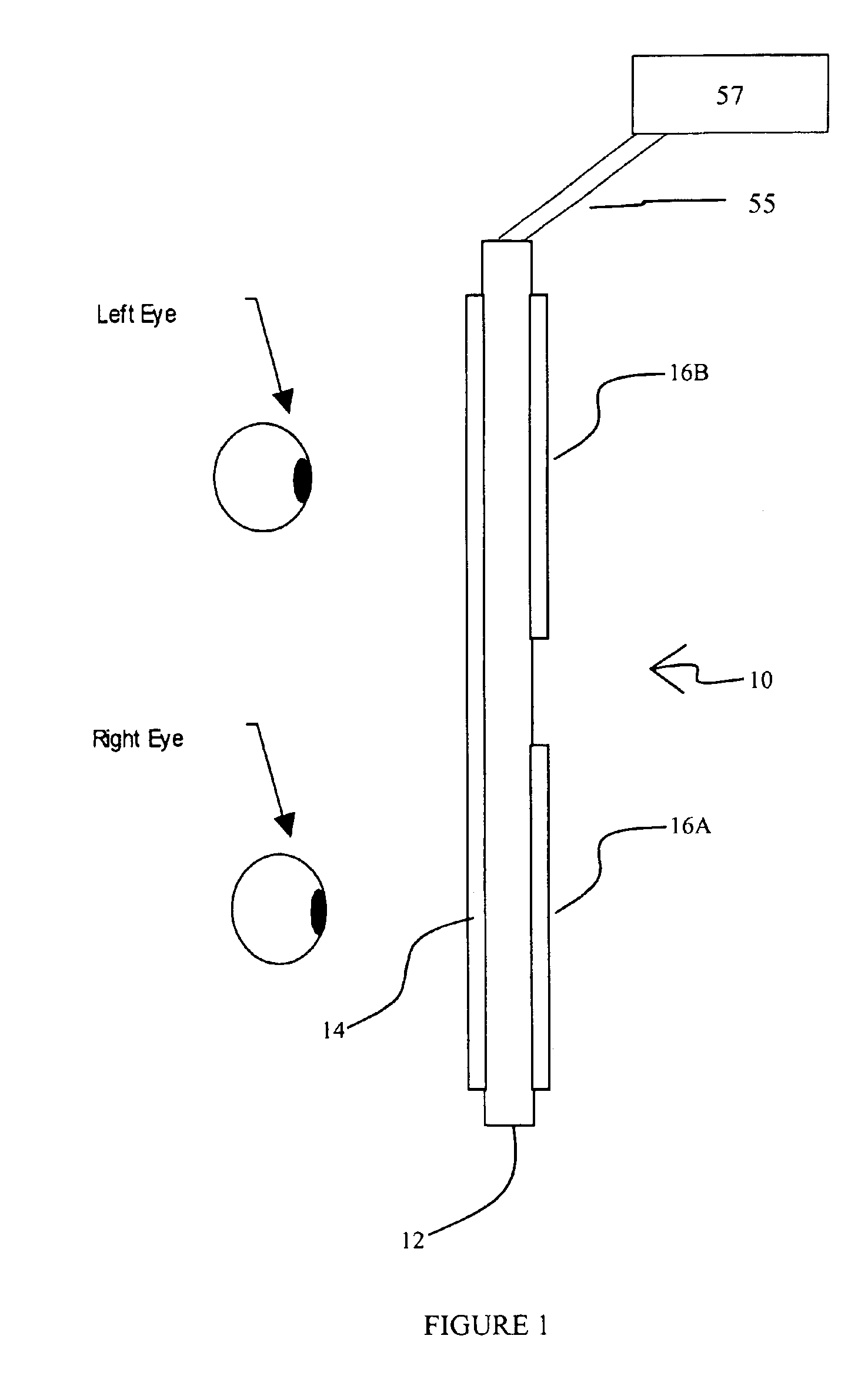
[0012]FIG. 1 illustrates a top view of the compound liquid crystal shutter assembly 10. The LC cell itself may be constructed from any of the various methods known to the art including twisted nematic, Ferro-electric, and pi-cell, etc.. The LC cell is constructed using a flexible substrate 12 to allow bending of the cell in one dimension. One side of the shutter assembly 10 is a laminated with a linear polarizing film designated P1. The other side is laminated with two separate linearly polarizing films that correspond to each eye 16A and 16B One film 16A is oriented such that its polarization axis is parallel to P1. The other film 16B is oriented such that its polarization axis is perpendicular to P1 and known as P2. A simplified control system 57 is electrically coupled to the LC cell 12 by means of a pair of wires 55. The order of the elements relative to the viewer's eye is not critical.

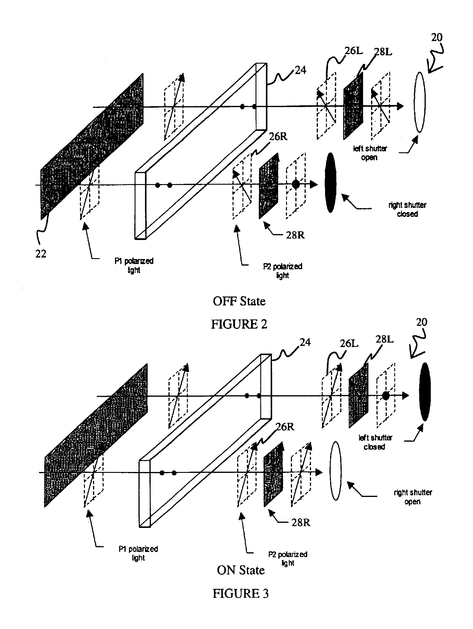
[0013]FIG. 2 illustrates an operational diagram of the compound LC shutter system 20 in which...


PUM


Abstract

The invention is a stereoscopic shutter system having a single liquid crystal (LC) cell. The system may have flexible substrates or non-flexible substrates. The system requires only two electrical conductors to shutter both eyes. The system uses twisted nematic liquid crystal, ferro-electric liquid crystal, pi-cell technology, or other similar shuttering technologies. The system includes only one LC cell, a single large laminated linearly polarizing filter P1, and two smaller linear polarizing analyzers oriented in the P1 and P2 states. The shutters may be bent into a one-dimensional curved shape about the vertical or horizontal axis.

Description

[0001]This application claims the benefit of provisional application No. 60 / 289,095, filed May 07, 2001.BACKGROUND OF THE INVENTION[0002]This invention relates to the field of stereoscopic viewing and in particular to the use of single cell liquid crystal shutter glasses.[0003]Typical Liquid Crystal (LC) shutter glasses are composed of two separate liquid crystal shutters that open and closed in an alternating pattern that is synchronized to the command of an image display system. Further, current systems use LC cells that are constructed from glass substrates that are non-flexible and limit the range of designs achievable for the glasses. The present invention offers a new approach to the construction of LC shutter glasses by using a single flexible LC cell as the active element. The advantages of the present invention over prior art include a simpler drive scheme requiring only two wires, lower cost due to a single larger LC cell, a flexible substrate allowing simple curvature of ...

Claims


Application Information

Patent Timeline
IPC IPC(8): G02C7/00G02C7/10G02F1/1335G02F1/13G02B27/22H04N13/00G02F1/1343G02C7/12
CPCG02B27/2264G02C7/101G02C7/12G02F1/133528H04N13/0438H04N13/0497G02F1/134309H04N2213/008G02B30/24H04N13/341H04N13/398
Inventor DIVELBISS, ADAM W.SWIFT, DAVID C.
Owner REVEO
Why Eureka
Try Eureka