AI technical title is built by PatSnap AI team. It summarizes the technical point description of the patent document.
a network policy and object model technology, applied in the field of computer networks, can solve problems such as accidental release of vital information from within, increased risks of flexible and streamlined computer and computer network, and inability to meet the needs of users, etc., and achieve the effect of simplifying policy managemen
Inactive Publication Date: 2005-09-13
ALCATEL-LUCENT USA INC
View PDF52 Cites 255 Cited by
Summary
Abstract
Description
Claims
Application Information
AI Technical Summary
This helps you quickly interpret patents by identifying the three key elements:
Problems solved by technology
Method used
Benefits of technology
Benefits of technology
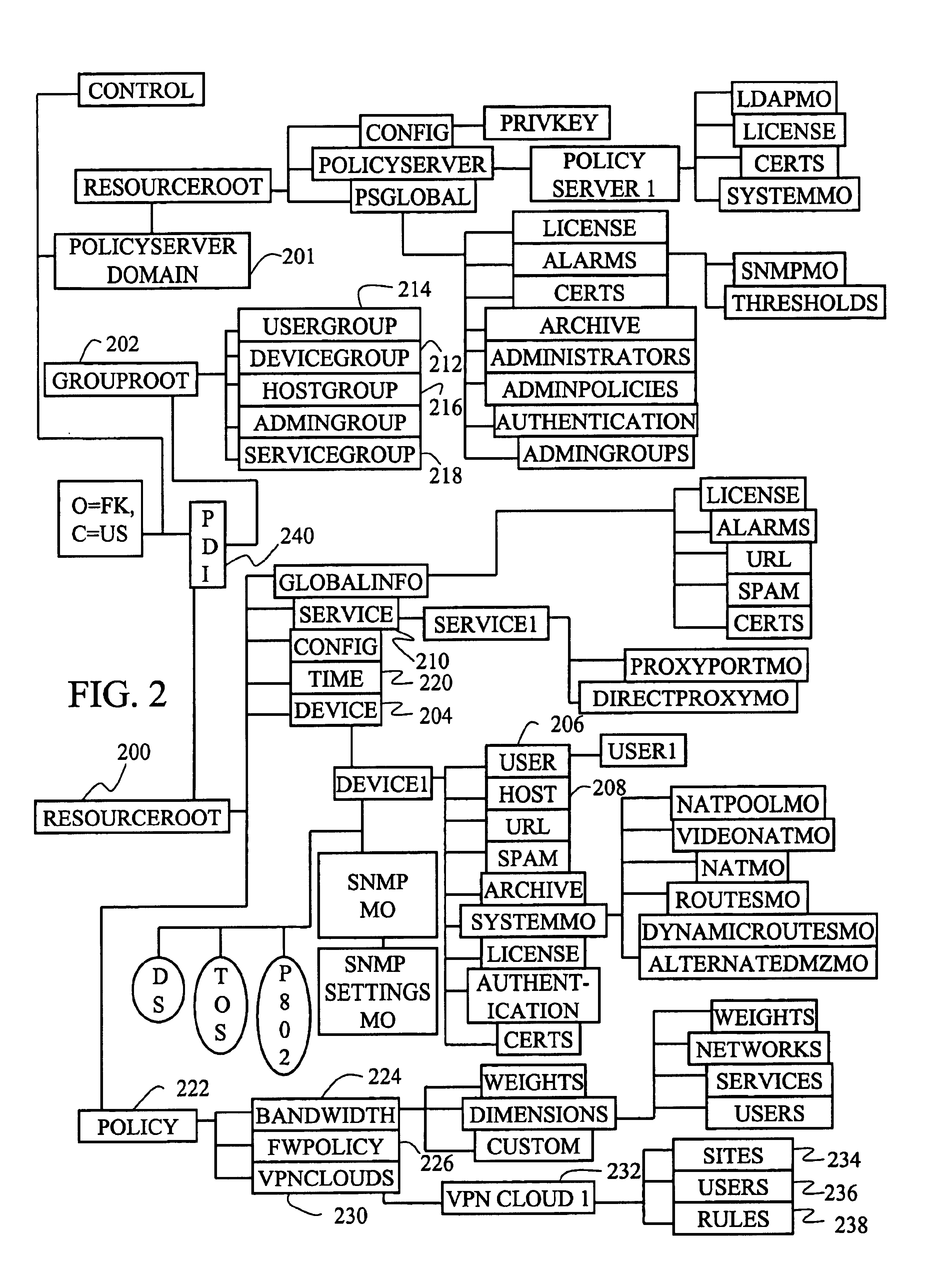
[0009]The central policy server is also associated with a central database storing configuration information of the first and second edge devices. The central database is organized according to a hierarchical object oriented structure for simplifying policy management.
[0013]It should be appreciated, therefore, that the hierarchical object oriented structure of the present invention helps simplify policy management by allowing the various elements of the policy management system to be defined and organized in an intuitive and extensible fashion.
Problems solved by technology
However, the flexibility and efficiencies provided by such computers and computer networks come with increasing risks, including security breaches from outside the corporation, accidental release of vital information from within it, and inappropriate use of the LAN, WAN, Internet, or extranet.
Furthermore, as an organization grows and spreads across multiple locations, the devices maintained also multiplies, multiplying the associated expenditures and efforts to configure, manage, and monitor the devices.
In fact, there are many obstacles and challenges in adopting such an approach.
One of these challenges is devising a scheme for specifying and distributing policy management information effectively across the entire organization.
Method used
Image
Click on the blue label to locate the original text in one second.
Reading with bidirectional positioning of images and text.
Examples
Embodiment Construction
[0045]I. Unified Policy Management System Architecture
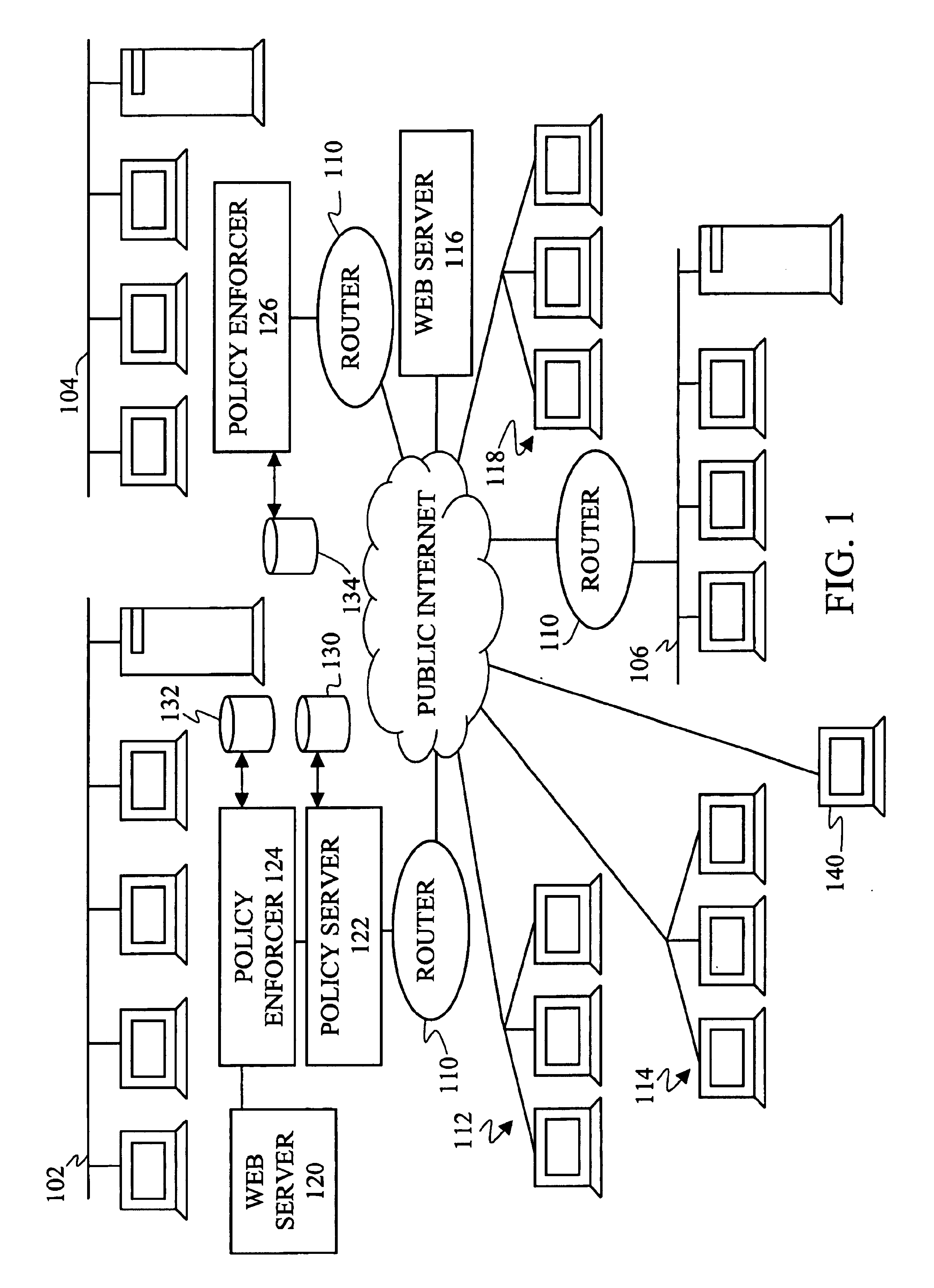
[0046]FIG. 1 is a schematic block diagram of an exemplary unified policy management system according to one embodiment of the invention. As illustrated in FIG. 1, private local networks 102, 104, and 106 are all coupled to a public network such as the Internet 108 via respective routers (generally identified at 110) and Internet Service Providers (ISPs) (not shown). Also coupled to the public Internet 108 via the ISPs are web surfers 112, dial-up network users 114, servers providing unauthorized web sites 116, email spammers 118 sending out unsolicited junk email, and remote VPN clients 140 seeking access to the private local networks 102.
[0047]According to one example, local network 102 connects users and resources, such as workstations, servers, printers, and the like, at a first location of the organization, such as the organization's headquarters, and local network 104 connects users and resources at a second location of the ...
PUM
Abstract
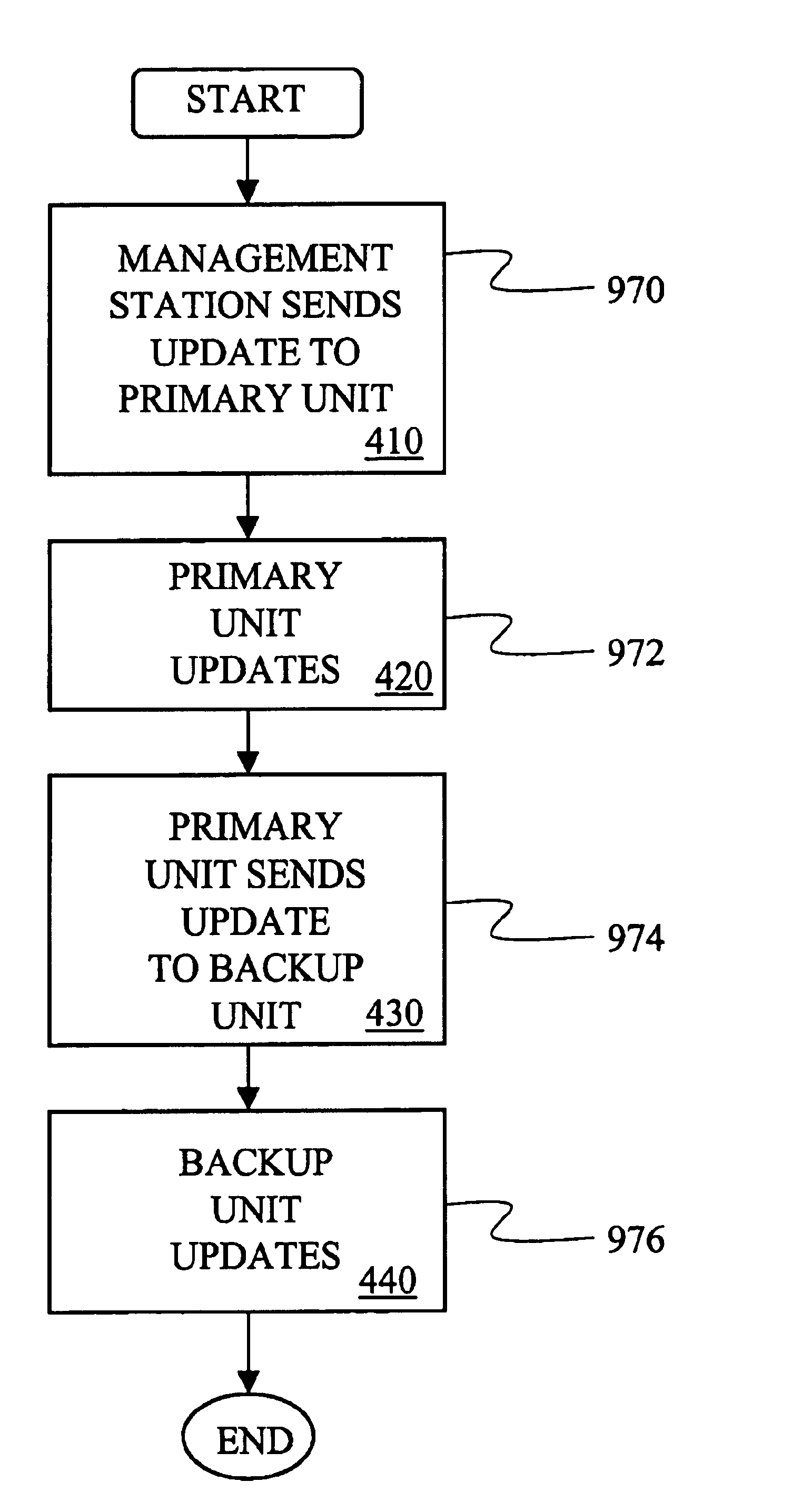
A unified policy management system for an organization including a central policy server and remotely situated policy enforcers. A central database and policy enforcer databases storing policy settings are configured as LDAP databases adhering to a hierarchical object oriented structure. Such structure allows the policy settings to be defined in an intuitive and extensible fashion. Changes in the policy settings made at the central policy server are automatically transferred to the policy enforcers for updating their respective databases. Each policy enforcer collects and transmits health and status information in a predefined log format and transmits it to the policy server for efficient monitoring by the policy server. For further efficiencies, the policy enforcement functionalities of the policy enforcers are effectively partitioned so as to be readily implemented in hardware. The system also provides for dynamically routed VPNs where VPN membership lists are automatically created and shared with the member policy enforcers. Updates to such membership lists are also automatically transferred to remote VPN clients. The system further provides for fine grain access control of the traffic in the VPN by allowing definition of firewall rules within the VPN. In addition, policy server and policy enforcers may be configured for high availability by maintaining a backup unit in addition to a primary unit. The backup unit becomes active upon failure of the primary unit.
Description
CROSS-REFERENCE TO RELATED APPLICATIONS[0001]This application claims the benefit of U.S. provisional application Nos. 60 / 138,849, 60 / 138,850, 60 / 139,033, 60 / 139,034, 60 / 139,035, 60 / 139,036, 60 / 139,038, 60 / 139,042, 60 / 139,043, 60 / 139,044, 60 / 139,047, 60 / 139,048, 60 / 139,049, 60 / 139,052, 60 / 139,053, all filed on Jun. 10, 1999, and U.S. provisional application No. 60 / 139,076, filed on Jun. 11, 1999, the contents of all of which are incorporated herein by reference. This application also contains subject matter that is related to the subject matter disclosed in U.S. patent application Ser. Nos. 09 / 591,802, 09 / 592,079, 09 / 592,163, 09 / 592,165, 09 / 592,442, 09 / 592,443, 09 / 591,801 now U.S. Pat. No. 6,708,187, and Ser. No. 09 / 592,083 now U.S. Pat. No. 6,678,835.FIELD OF THE INVENTION[0002]The present invention relates to computer networks, and more particularly, to devices and methods for specifying and distributing policy management information effectively to remote private networks across th...
Claims
Application Information
Patent Timeline
Application Date:The date an application was filed.
Publication Date:The date a patent or application was officially published.
First Publication Date:The earliest publication date of a patent with the same application number.
Issue Date:Publication date of the patent grant document.
PCT Entry Date:The Entry date of PCT National Phase.
Estimated Expiry Date:The statutory expiry date of a patent right according to the Patent Law, and it is the longest term of protection that the patent right can achieve without the termination of the patent right due to other reasons(Term extension factor has been taken into account ).
Invalid Date:Actual expiry date is based on effective date or publication date of legal transaction data of invalid patent.

