Control device and method for monitoring wear parts for printers and copiers

a technology for copiers and wear parts, applied in optics, instruments, electromagnetography, etc., can solve problems such as complete standstill of printing operations, and achieve the effect of reducing operating costs and deteriorating the dependability of printers or copiers

Inactive Publication Date: 2005-09-13
OCE PRINTING SYST
View PDF22 Cites 17 Cited by
  • Summary
  • Abstract
  • Description
  • Claims
  • Application Information

AI Technical Summary

Benefits of technology

[0009]The present invention provides a control device and a method for monitoring wear parts for printers and copiers in order to reduce the consumer costs of the printer or copier.
[0012]As a result, it is possible to individually set the replacement and maintenance intervals for the individual wear parts and to thus adapt them to different applications or environmental conditions. Thus, wear parts that are subject to less wear due to certain conditions can be retained longer in the printer or copier, and wear parts that are correspondingly more heavily used can be replaced correspondingly faster. This results in a considerable reduction in the operating costs without deteriorating the dependability of the printer or copier.

Problems solved by technology

This prevents the printer or copier from continuing to operate with parts that are no longer suitable, which could result in the occurrence of malfunctions in the printing operation that could lead to a complete standstill of printing operations.

Method used


Image

  • Control device and method for monitoring wear parts for printers and copiers
  • Control device and method for monitoring wear parts for printers and copiers
  • Control device and method for monitoring wear parts for printers and copiers

Examples


Embodiment Construction

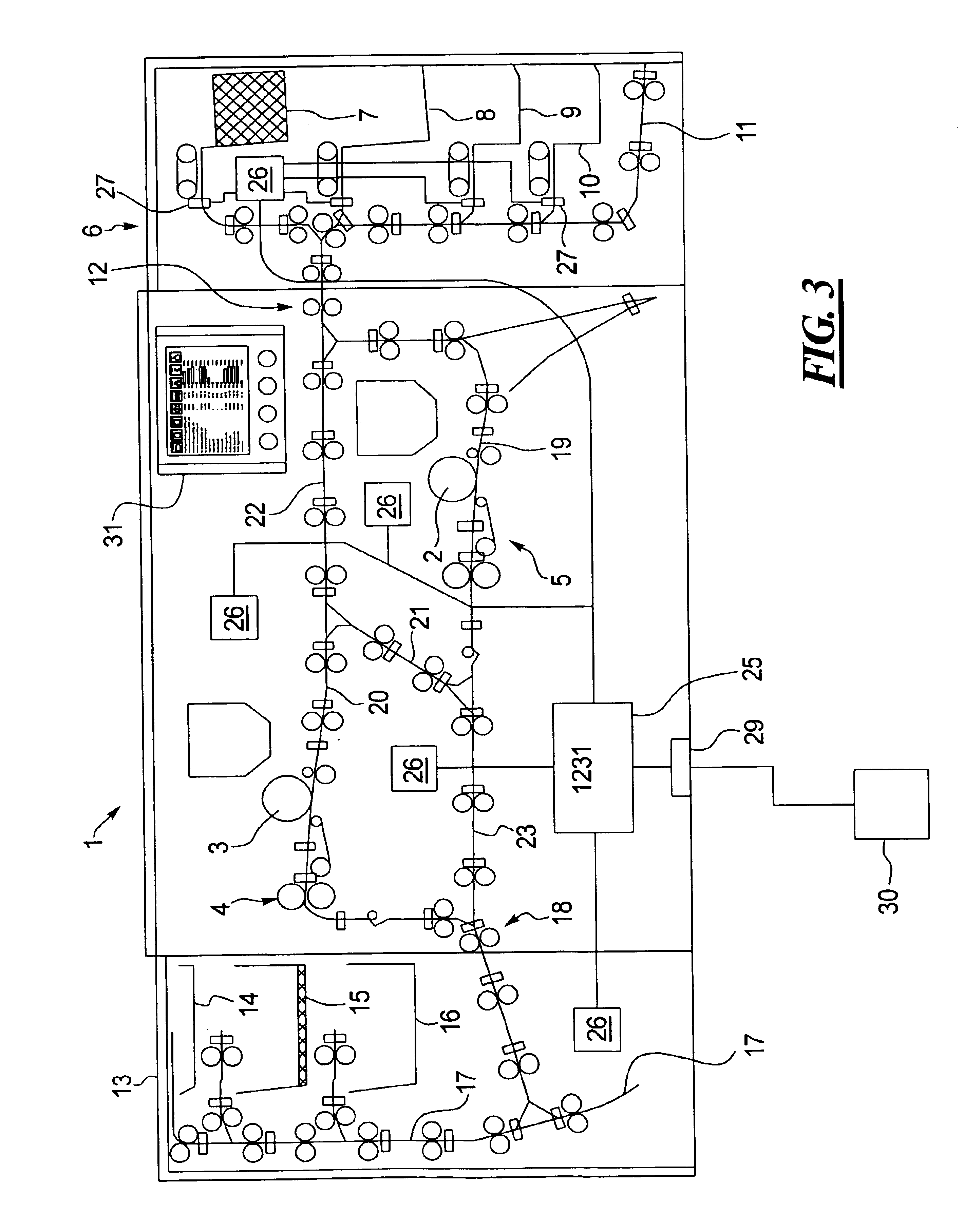
[0019]FIG. 3 shows a high-performance printer 1 that serves for fast printing of sheets of paper. The high-performance printer 1 contains a first, lower printing unit 2 as well as a second, upper printing unit 3. Both printing units 2 and 3 work according to the known electrographic process and with the same transfer printing speed. The printing units 2 and 3 are followed by fixing devices 4 and 5 that are schematically shown in FIG. 3. A paper input 6 is connected to the high-performance printer 1, the paper input 6 containing a plurality of supply containers 7-10 with single sheets as well as an external paper input channel 11 via which single sheets can be delivered from the outside via preceding, optional input units or, respectively, a paper pre-processor. Individual sheets are supplied to an input section 12 via a transport channel. A paper output 13 containing a plurality of output containers 14-16 is connected to the high-performance printer 1 at the output side. Two output ...


PUM


Abstract

A control device and a method for monitoring wear parts for printers and copiers is provided. The control device includes a counter device with which the replacement intervals or, respectively, the maintenance intervals for individual wear parts are monitored. The replacement and maintenance intervals can be individually set, so that they can be matched to the respective use conditions of the printer.

Description

BACKGROUND OF THE INVENTION[0001]1. Field of the Invention[0002]The present invention is in general directed to a control device and to a method for monitoring wear parts for printers and copiers. The invention is in particular provided for electrophotographically working printers and copiers.[0003]2. Description of the Related Art[0004]Electrophotographic printers are disclosed, for example, by German Patent Document DE 34 16 252 A1, European Patent Document EP 0 104 022 A2, German Letters Patent 1,280,605, German Patent Document DE 34 07 847 A1, and Published International Applications WO 91 / 13386 or WO 98 / 18052.[0005]Published International Application WO 98 / 18052 discloses a printer with two identical printing units to which page-shaped material to be printed is supplied via a common input section. The printed material is output via a common output section.[0006]Such printers and copiers are provided with a counting device for counting the number of printed sheets. Respective th...

Claims


Application Information

Patent Timeline
Patent Type & Authority Patents(United States)
IPC IPC(8): G03G15/00
CPCG03G15/553G03G15/55G03G15/5079
Inventor HOLZNER, BERNHARD
Owner OCE PRINTING SYST
Why Eureka
Try Eureka