Holographic recording medium and recording method

Inactive Publication Date: 2005-09-22
FUJIFILM BUSINESS INNOVATION CORP
View PDF10 Cites 16 Cited by
  • Summary
  • Abstract
  • Description
  • Claims
  • Application Information

AI Technical Summary

Benefits of technology

[0012] Accordingly, the present invention has been developed in the light of the problems above and provides a holographic recording medium and a holographic recording method, which allow rewriting of data and are excellent in data retention.
[0016] The optical filter layer is formed at least on one side of the optical recording layer. The optical filter layer allows transmission of the writing light and a reading light having a predetermined wavelength irradiated on the optical recording layer, for reproducing the hologram recorded on the optical recording layer, and blocks light having a shorter wavelength than the wavelength of the writing light. Therefore, light absorption ratio of the optical recording layer can be reduced, without interfering with writing and reading of the hologram. Consequently, the hologram recorded on the optical recording layer is not destroyed by external light, such as the sunlight, enabling data to be retained for a long period of time.
[0017] The optical filter layer of the holographic recording medium, as described above, may comprise an absorption filter, that selectively absorbs light having a shorter wavelength than the wavelength of the writing light. Examples of such absorption filters include glass substrates and polymer films containing light absorbing agents that selectively absorb light having a shorter wavelength than the wavelength of the writing light. UV absorbing agents and pigments may be used as the light absorbing agents. The optical filter layer may also comprise a reflection filter that selectively reflects light having a shorter wavelength than the wavelength of the writing light. An example of a reflection filter available is a dielectric multilayer film. Since reflection filters do not emit heat, they are preferable for improving data retention ability. Reflection filters are also advantageous in that transmittance at the wavelength of the transmitting light, such as the writing light, is high.
[0020] The first optical filter layer is formed on one side of the optical recording layer, and the first optical filter layer allows transmission of the writing light while blocking light having a shorter wavelength than the wavelength of the writing light. Accordingly, the light absorption ratio of the optical recording layer may be reduced, without interfering with the recording of the hologram, by irradiating the writing light from the first optical filter layer side and effecting hologram recording. The second optical filter layer is formed on the other side of the optical recording layer. The second optical filter layer allows transmission of a reading light having a predetermined wavelength and irradiated on the optical recording layer, for reproducing a hologram recorded on the optical recording layer, therethrough and blocks light having a shorter wavelength than the wavelength of the reading light. Consequently, by reproducing the hologram by irradiating the reading light from the second optical filter layer side, the light absorption ratio of the optical recording layer can be reduced without interfering with reading of the hologram.
[0021] Since the light absorption ratio of the optical recording layer is reduced, by using the first optical filter layer and second optical filter layer, the hologram recorded on the optical recording layer is not destroyed by external light, such as sunlight, enabling date to be retained for a long period of time.

Problems solved by technology

Accordingly, it is pointed out that the material is liable to cause optical aberration and handling of the material is difficult.
However, in the holographic recording medium taking advantage of the photoisomerization reaction as described above, optical anisotropy induced in the polymer film is not stabilized (i.e., a fixing process is not carried out) after recording a hologram, so that the recording medium remains rewritable.
Accordingly, there arises a problem in that optical anisotropy is induced by exposing the recording medium to external light, such as the sunlight, after recording, and the recorded hologram can be destroyed.

Method used


Image

  • Holographic recording medium and recording method
  • Holographic recording medium and recording method
  • Holographic recording medium and recording method

Examples


first embodiment

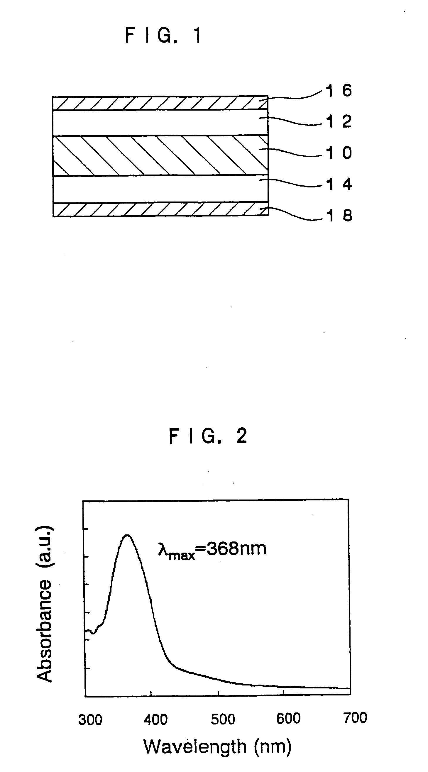
[0031] The holographic recording medium of a first embodiment, as shown in FIG. 1, includes: an optical recording layer 10 capable of recording a hologram; a pair of transparent substrates 12 and 14 sandwiching the optical recording layer 10; and optical filter layers 16 and 18, formed respectively on the surfaces of the transparent substrates 12 and 14. The optical filter layers 16 and 18 allows transmission of a predetermined wavelength of a writing light and a predetermined wavelength of a reading light, while blocking light having a wavelength shorter than the wavelength of the writing light.

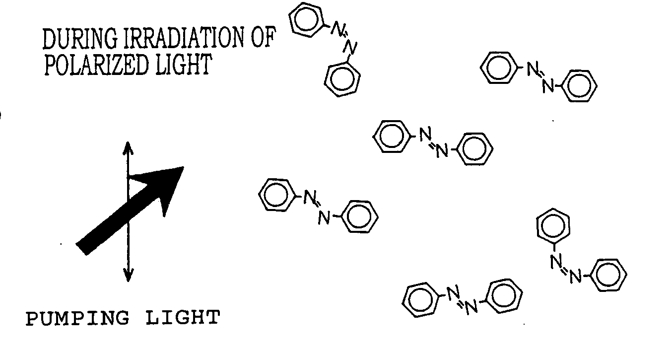
[0032] A hologram is recorded on the holographic recording medium by inducing optical anisotropy by irradiating the writing light, having a predetermined wavelength, and comprising a signal beam and reference beam onto the optical recording layer 10. The recorded hologram is reproduced by irradiating the reading light of a predetermined wavelength onto the optical recording layer 10. Since ...

second embodiment

[0058] The holographic recording medium according to the present embodiment is a laminate comprising an optical recording layer 10 capable of recording a hologram, and a pair of filter substrates 20 and 22 sandwiching the optical recording layer 10 (See FIG. 5). The same reference numerals are given to the same components as in the holographic recording medium in the first embodiment, and descriptions thereof will be omitted.

[0059] The filter substrates 20 and 22 have a filter function for allowing transmission of the writing light and reading light, while blocking a light having a shorter wavelength than the wavelength of the writing light. The filter substrates 20 and 22 preferably also have a filter function for blocking light having a longer wavelength than the wavelength of the writing light, from the view point of reducing the light absorption ratio of the optical recording layer.

[0060] Plastic substrates containing colorants dissolved or dispersed therein may also be used a...

third embodiment

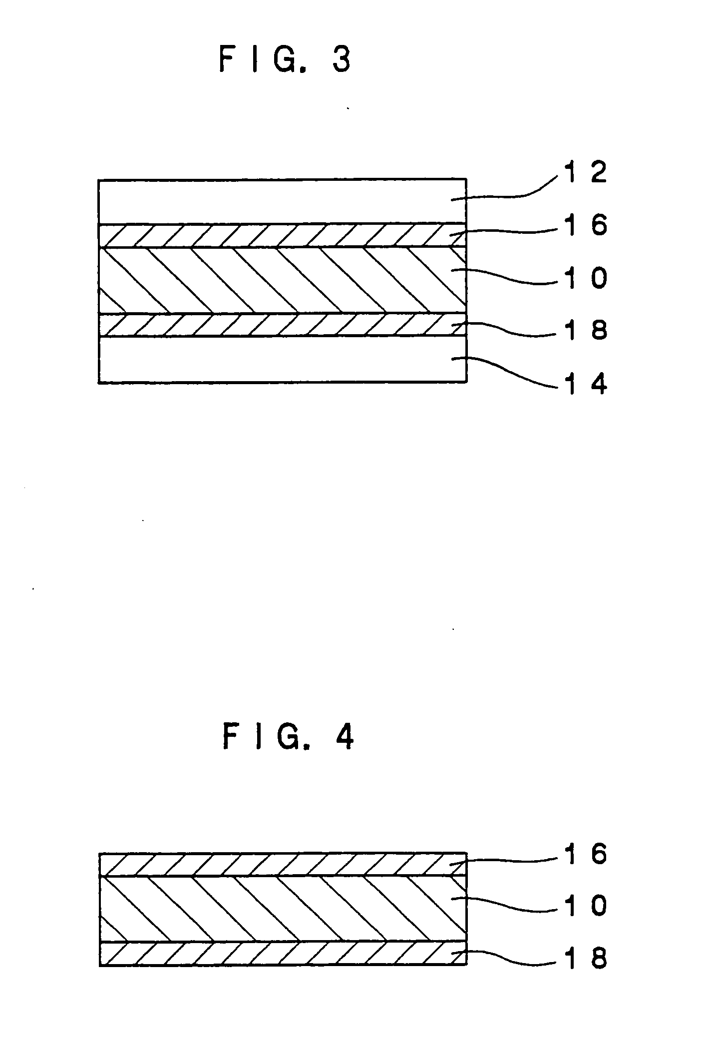
[0065] The holographic recording medium according to the present embodiment comprises, as shown in FIG. 6, a laminate comprising: an optical recording layer 10 capable of recording a hologram; a pair of transparent substrates 12 and 14, sandwiching the optical recording layer 10; a first optical filter layer 24 formed on the surface of the transparent substrate 12, for allowing transmission of a writing light having a predetermined wavelength and for blocking light having a shorter wavelength than the wavelength of the writing light; and a second optical filter layer 26 formed on the surface of the transparent substrate 14, for allowing transmission of a reading light having a predetermined wavelength and for blocking light having a shorter wavelength than the wavelength of the reading light. The same reference numerals are given to the same components as in the holographic recording medium in the first embodiment, and descriptions thereof will be omitted.

[0066] The hologram is rec...


PUM


Abstract

The present invention provides a holographic recording medium comprising: an optical recording layer, which optical recording layer includes one of a polymer compound having photoisomerizable groups in the side chain thereof and a polymer compound in which photoisomerizable molecules are dispersed therein, which recording layer records a hologram by having optical anisotropy induced by irradiation with a writing light having a predetermined wavelength thereon; and an optical filter layer formed on at least one side of the optical recording layer, which optical filter layer allows transmission of the writing light and a reading light having a predetermined wavelength irradiated on the optical recording layer, for reproducing the hologram recorded on the optical recording layer, therethrough and blocks light having a shorter wavelength than the wavelength of the writing light.

Description

CROSS-REFERENCE TO RELATED APPLICATION [0001] This application claims priority under 35 USC 119 from Japanese Patent Application No. 2004-83590, the disclosure of which is incorporated by reference herein. BACKGROUND OF THE INVENTION [0002] 1. Technical Field [0003] The present invention relates to a holographic recording medium and recording method for recording a hologram, in particular to a data-rewritable hologram recording medium and recording method. [0004] 2. Description of the Related Art [0005] Recently holographic memories which take advantage of the high density recordability of holograms are being actively investigated for use as the next generation of high-speed, high-capacity memory. Hitherto, inorganic photorefractive crystals, typified by lithium niobate (LiNbO3), have been used for recording materials in data-rewritable hologram recording media. However, refractive index changes of the inorganic photorefractive crystal are as small as 1 in 10,000, and the recording ...

Claims


Application Information

Patent Timeline
IPC IPC(8): G02B5/22G02B5/26G03H1/02G03H1/04G11B7/0065G11B7/24G11C13/04
CPCG03H1/02G03H2001/026G03H2001/0264G03H2250/39G11C13/045G11B7/0065G11B7/2403G11B7/24044G11B7/24056G03H2260/51
Inventor FURUKI, MAKOTOKAWANO, KATSUNORITAKIZAWA, HIROO
Owner FUJIFILM BUSINESS INNOVATION CORP
Why Eureka
Try Eureka