Electrical connector and method of making the same

Inactive Publication Date: 2005-02-24
HON HAI PRECISION IND CO LTD
View PDF4 Cites 1 Cited by
  • Summary
  • Abstract
  • Description
  • Claims
  • Application Information

AI Technical Summary

Benefits of technology

[0011] Another object of the present invention is to provide a method to make an electrical connector with an excellent retention between a contact and a housing thereof.

Problems solved by technology

As a result, the structure of the connector turns to be increasingly complex and manufacturing of the electrical connector becomes increasingly difficult.

Method used


Image

  • Electrical connector and method of making the same
  • Electrical connector and method of making the same
  • Electrical connector and method of making the same

Examples


Embodiment Construction

[0027] Reference will now be made to the drawings to describe the present invention in details.

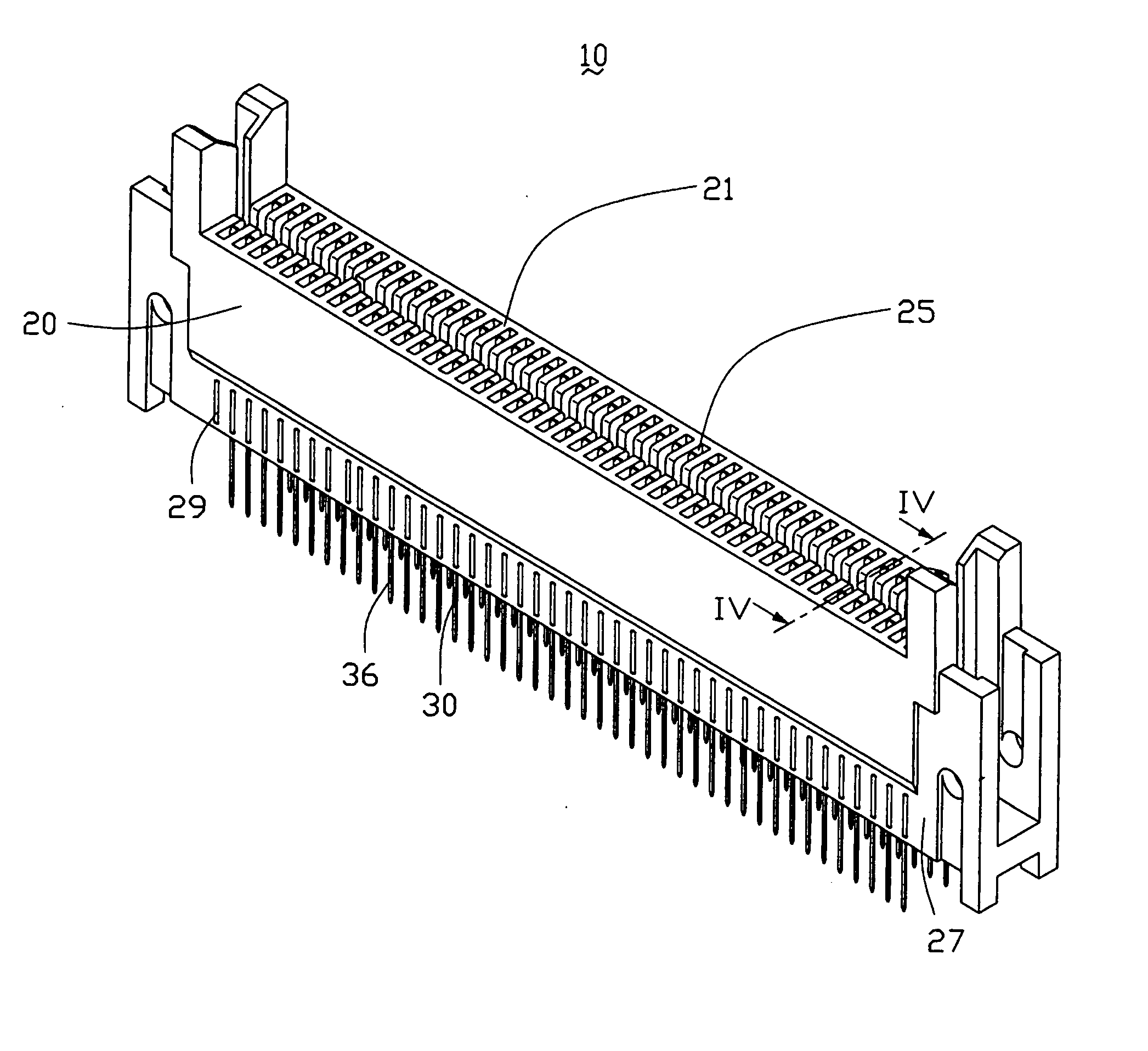
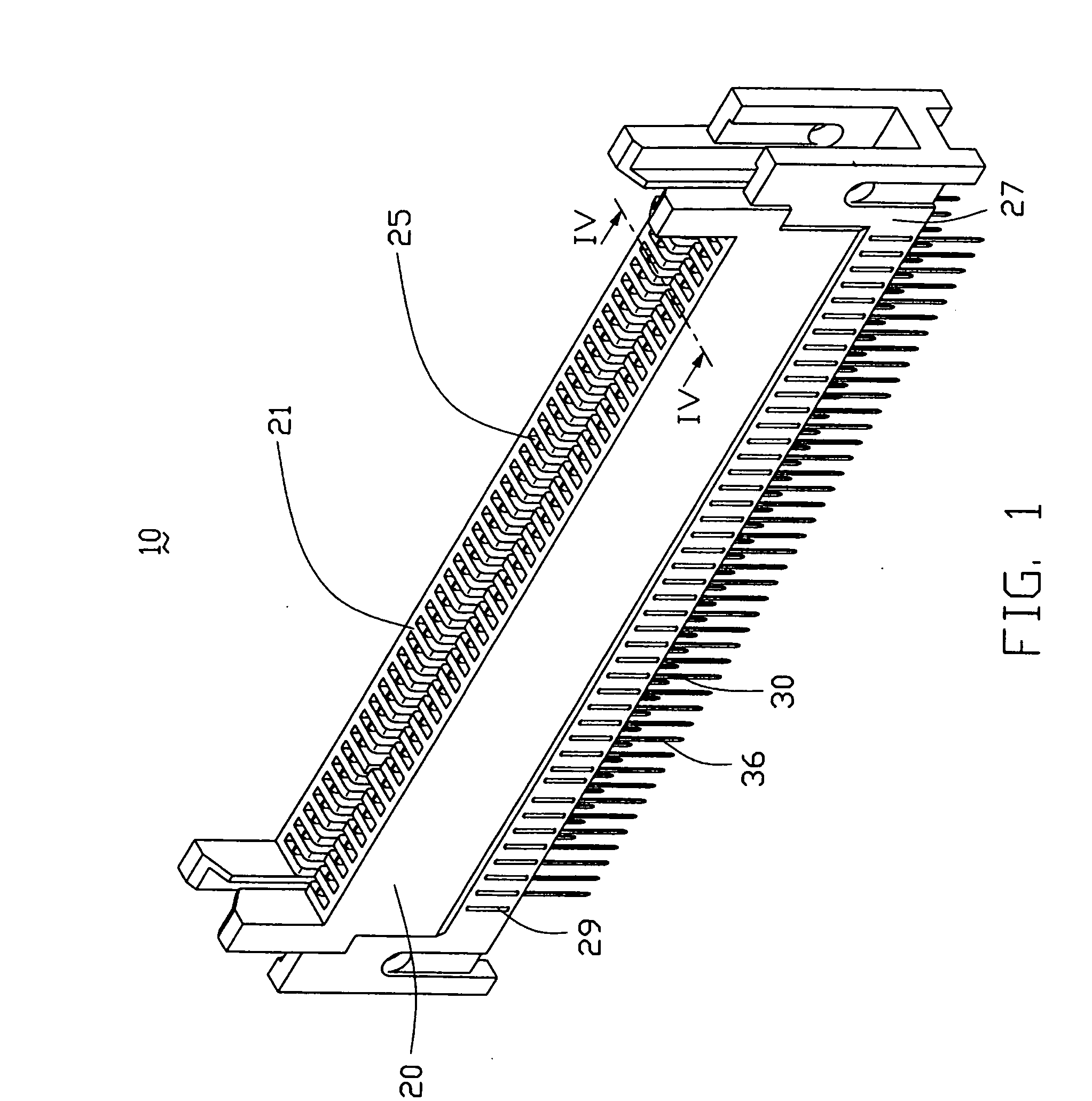
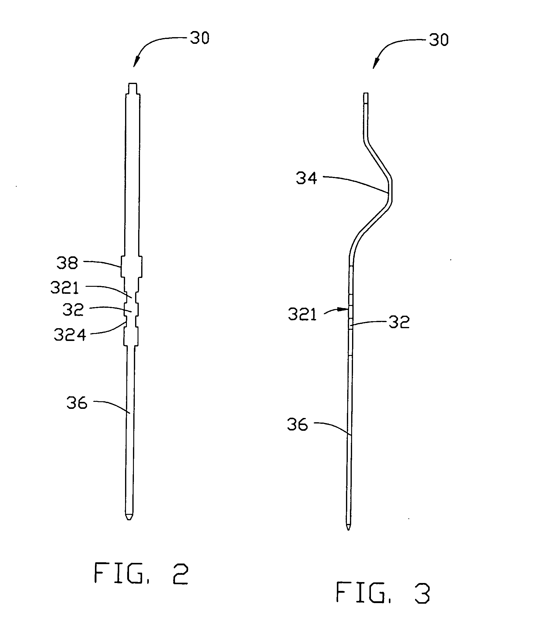
[0028] Referring to FIG. 1, an electrical connector 10 in accordance with a preferred embodiment of the present invention is shown. The connector 10 is mainly used for connecting a memory module (not shown) or the like to a printed circuit board (not shown). The connector 10 includes a longitudinal dielectric housing 20 and a number of contacts 30 received in the housing 20.

[0029] Referring to FIGS. 1, 4 and 5, the dielectric housing 20 defines a installing surface 22, an inserting surface 21 opposite to the installing surface 22 and a first outside face 23 perpendicular to both the installing surface 22 and the inserting surface 21. There is a second outside face 27 connected parallel to the first outside face 23 by a step. A lengthwise trench 24 for receiving the memory module is defined in the middle of the inserting surface 21. The housing 20 forms a longitudinal bottom wall 28 and t...


PUM


Abstract

An electrical connector includes a dielectric housing and a number of contacts. One side of the dielectric housing defines a number of through passageways for receiving the contacts. The contact includes a retention portion to secure the contact in the dielectric housing. The retention portion defines at least one sunken portion. The housing is stamped out a corresponding number of projecting portions after the contacts are inserted into the housing. The projecting portions engage into sunken portions of the contacts, thereby securing the contacts in the housing.

Description

BACKGROUND OF THE INVENTION [0001] 1. Field of The Invention [0002] The present invention relates to an art of electrical connectors, more specifically, to an electrical connector for electrically connecting a memory module or the like to a printed circuit board. [0003] 2. Description of Related Art [0004] With the development of electronic industry, miniaturization and high speed of an electrical connector is increasingly required. As a result, the structure of the connector turns to be increasingly complex and manufacturing of the electrical connector becomes increasingly difficult. For example, in order to prevent terminals from loosening in a housing of the electrical connector, a conventional technology is provided to stamp one side of the housing where the terminal is secured nearby. Therefore, an interference between the terminal and the housing is gained by proper deformation of the housing by stamping, which provide a firm securing of the terminal in the housing. [0005] Ref...

Claims


Application Information

Patent Timeline
IPC IPC(8): H01R12/18H01R13/41
CPCH01R12/716H01R13/41
Inventor HUANG, HUA YINLIN, NICK
Owner HON HAI PRECISION IND CO LTD
Why Eureka
Try Eureka