RFID tag having combined battery and passive power source

a technology of rfid tags and batteries, applied in the field of rfid transponders, can solve the problems of unusable rfid tags, limited life expectancy of battery-powered rfid tags, and tend to require a shorter distan

Inactive Publication Date: 2005-09-13
INTERMEC IP
View PDF16 Cites 115 Cited by
  • Summary
  • Abstract
  • Description
  • Claims
  • Application Information

AI Technical Summary

Benefits of technology

[0007]The present invention provides an RFID tag that is powered both by an internal battery and passively by an ...

Problems solved by technology

A drawback of passive RFID tags is that they tend to require a shorter distance between the RFID tag and the RFID reader (known as the read range) in comparison to battery-powered RFID tags.
Unlike passive RFID tags, battery-powered RFID tags have a limited life expectancy.
Once the ...

Method used


Image

  • RFID tag having combined battery and passive power source
  • RFID tag having combined battery and passive power source

Examples


Embodiment Construction

[0012]The present invention satisfies the need for an RFID tag having the attributes of both battery-powered and passively-powered tags. In the detailed description that follows, like element numerals are used to describe like elements illustrated in one or more of the figures.

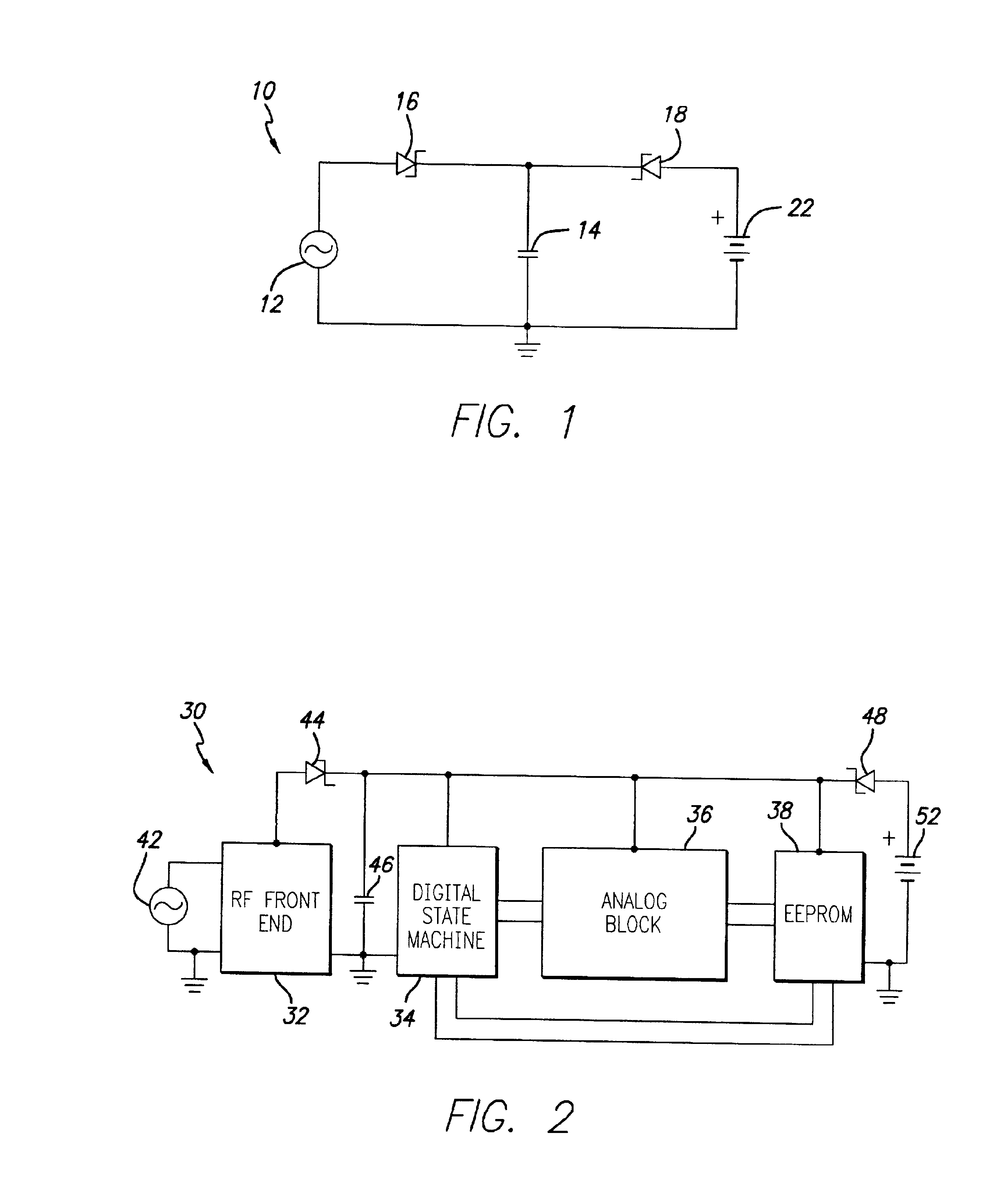
[0013]Referring first to FIG. 1, a block diagram of an embodiment of a dual power mode circuit 10 for an RFID tag in accordance with the present invention is illustrated. The dual power mode circuit 10 includes an RF source 12, an energy storage capacitor 14, a first diode 16, a second diode 18, and a battery 22. The RF source 12 is provided by the interrogating RF field transmitted by an RFID reader, that is rectified by the RF front end of the RFID tag (not shown in FIG. 1). The energy storage capacitor 14 serves as a voltage source for the remaining circuitry of the RFID tag (not shown in FIG. 1), and is coupled to the RF source 12 and the battery 22 in separate, respective charging circuits. More particula...


PUM


Abstract

An RFID tag is powered both by an internal battery and passively by an interrogating RF field. As a result, the RFID tag can be passively powered after the internal battery has been depleted. More particularly, an embodiment of the RFID tag includes electronic circuitry to provide RFID functionality, and an energy storage device coupled to the electronic circuitry to provide an operational voltage thereto. A battery is operatively coupled to the energy storage device to charge the energy storage device. A rectified RF power source derived from an interrogating RF field is also operatively coupled to the energy storage-device to charge the energy storage device. The rectified RF power source and the battery are electrically separated from each other. The energy storage device remains charged by the battery in the absence of the RF interrogating field while the battery has remaining capacity. After the battery has become depleted, the energy storage device is charged by the presence of the RF interrogating field.

Description

BACKGROUND OF THE INVENTION[0001]1. Field of the Invention[0002]The present invention relates to radio frequency (RF) transponders, and more particularly, to a radio frequency identification (RFID) transponder that is powered by an internal battery and also has an ability to passively recover power from an interrogating RF field after the internal battery has become depleted.[0003]2. Description of Related Art[0004]In the automatic data identification industry, the use of RFID transponders (also known as RFID tags) has grown in prominence as a way to track data regarding an object to which the RFID transponder is affixed. An RFID tag generally includes a semiconductor memory in which digital information may be stored, such as an electrically erasable, programmable read-only memory (EEPROM) or similar electronic memory device. An RFID interrogator or reader may recover the digital information stored in the RFID tag using modulated radio frequency (RF) signals. One such communication ...

Claims


Application Information

Patent Timeline
IPC IPC(8): G06K19/07
CPCG06K19/0701G06K19/0702G06K19/0723
Inventor HEINRICH, HARLEY KENTPILLAI, VIJAY
Owner INTERMEC IP
Why Eureka
Try Eureka