Method for detecting fault on transmission lines by using harmonics and state transition diagram

a transmission line and harmonic technology, applied in the direction of instruments, nuclear elements, digital computer details, etc., can solve the problems of additional hardware, difficult to reliably detect the fault using the radio frequency component, and apparent impedance entering the zon

Inactive Publication Date: 2005-09-13
INTELLECTUAL DISCOVERY CO LTD
View PDF4 Cites 17 Cited by
  • Summary
  • Abstract
  • Description
  • Claims
  • Application Information

AI Technical Summary

Benefits of technology

[0008]Accordingly, the present invention has been made to solve the above-mentioned problems occurring in the prior art, and an object of the present invention is to provide a method for detecting a fault on transmission lines by using harmonics and a state transition diagram, in which two logic signals are outputted by using apparent impedance component of steady state characteristic and a sum of harmonics components of transient state characteristic, and such two logic signals are used as input parameters for the state transition diagram in such a manner that a state transition is generated in the state transition diagram according to a state of a system, thereby presuming the state of the system based on the state transition such that a distance relay is prevented from being malfunctioned even if load applied to the distance relay is increased or unstable voltage is applied to the distance relay.

Problems solved by technology

In addition, if voltage is reduced and current is increased due to an unstable state of voltage, apparent impedance may enter into the zone.
However, not only is an additional hardware required to extract the radio frequency component, but also it is difficult to reliably detect the fault by using the radio frequency component.

Method used


Image

  • Method for detecting fault on transmission lines by using harmonics and state transition diagram
  • Method for detecting fault on transmission lines by using harmonics and state transition diagram
  • Method for detecting fault on transmission lines by using harmonics and state transition diagram

Examples


Embodiment Construction

[0039]Hereinafter, a preferred embodiment of the present invention will be described with reference to the accompanying drawings. In the following description and drawings, the same reference numerals are used to designate the same or similar components, and so repetition of the description on the same or similar components will be omitted.

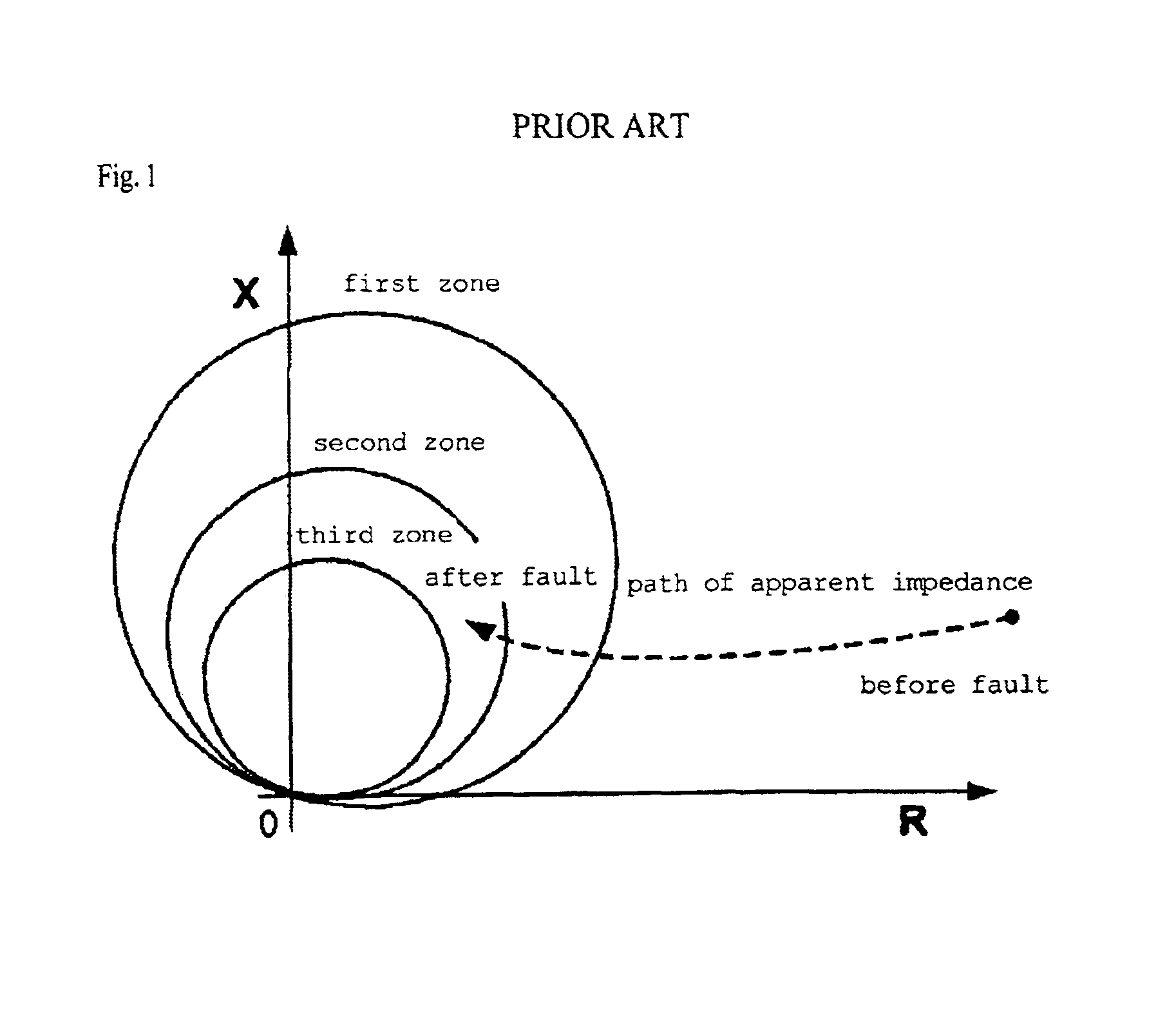
[0040]FIG. 1 is a view showing a path of apparent impedance in an impedance plane of a conventional distance relay. As shown in FIG. 1, apparent impedance is located out of a zone if a fault does not occur on a transmission line. However, apparent impedance enters into the zone when the fault occurs on the transmission line. The conventional method detects the fault by using apparent impedance entering into the zone.

[0041]Apparent impedance accesses to a starting point as a distance between a fault position and a convergence position of apparent impedance is shortened. Since a distance between the starting point and the convergence position of app...


PUM


Abstract

Disclosed is a method for detecting a fault by using harmonics and a state transition diagram. When the fault occurs on transmission lines, the fault is detected by using harmonics and the state transition diagram. Two logic signals are outputted by using apparent impedance of a steady state characteristic and a sum of harmonics components of a transient state characteristic. Such two logic signals are used as input parameters of the state transition diagram so that the state of an electric power system is presumed based on a state transition of the electric power system. It is possible to prevent a distance relay from being malfunctioned under an increase of load and unstable voltage. The state of the electric power system is presumed by using harmonics and the state transition diagram, and the fault on the transmission line is reliably detected.

Description

BACKGROUND OF THE INVENTION[0001]1. Field of the Invention[0002]The present invention relates to a method for detecting a fault on transmission lines, and more particularly to a method for precisely detecting a fault on transmission lines by using harmonics and a state transition diagram of an electric power system, in which apparent impedance having steady state characteristic and harmonics having transient state characteristic are used as input parameters of the state transition diagram so as to presume a state of the electric power system, thereby detecting the fault on the transmission lines even if the transmission lines are subject to unstable voltage and overload.[0003]2. Description of the Prior Art[0004]Distance relays use apparent impedance calculated by using voltage and current applied to lines. When a ground fault or a short circuit fault occurs on the lines, a value of apparent impedance of a distance relay is reduced. If apparent impedance having a reduced value enter...

Claims


Application Information

Patent Timeline
Patent Type & Authority Patents(United States)
IPC IPC(8): G01R31/00G06F19/00H02H3/42H02H3/05G01R31/02G01R31/08H02H3/40H02H3/52
CPCG01R31/088H02H3/40H02H3/52
Inventor KIM, CHUL-HWANHEO, JEONG-YONG
Owner INTELLECTUAL DISCOVERY CO LTD
Why Eureka
Try Eureka