System for venting noxious fumes from a toilet

a technology for venting systems and toilets, applied in the field of toilets, can solve problems such as inconvenient use and limit air flow when the system is inoperativ

Inactive Publication Date: 2005-09-20
CANALES JR AMADOR
View PDF14 Cites 11 Cited by
  • Summary
  • Abstract
  • Description
  • Claims
  • Application Information

AI Technical Summary

Benefits of technology

[0016]ACCORDINGLY, AN OBJECT of the present invention is to provide a system for venting noxious fumes from a toilet that avoids the disadvantages of the prior art.

Problems solved by technology

The system may also include a valve with dampers that allow air flow to enter the tank during flushing and allow air flow to exit the tank during venting, but that limits air flow when the system is inoperative.
Furthermore, even though these innovations may be suitable for the specific individual purposes to which they address, however, they would not be suitable for the purposes of the present invention as heretofore described.

Method used


Image

  • System for venting noxious fumes from a toilet
  • System for venting noxious fumes from a toilet
  • System for venting noxious fumes from a toilet

Examples


Embodiment Construction

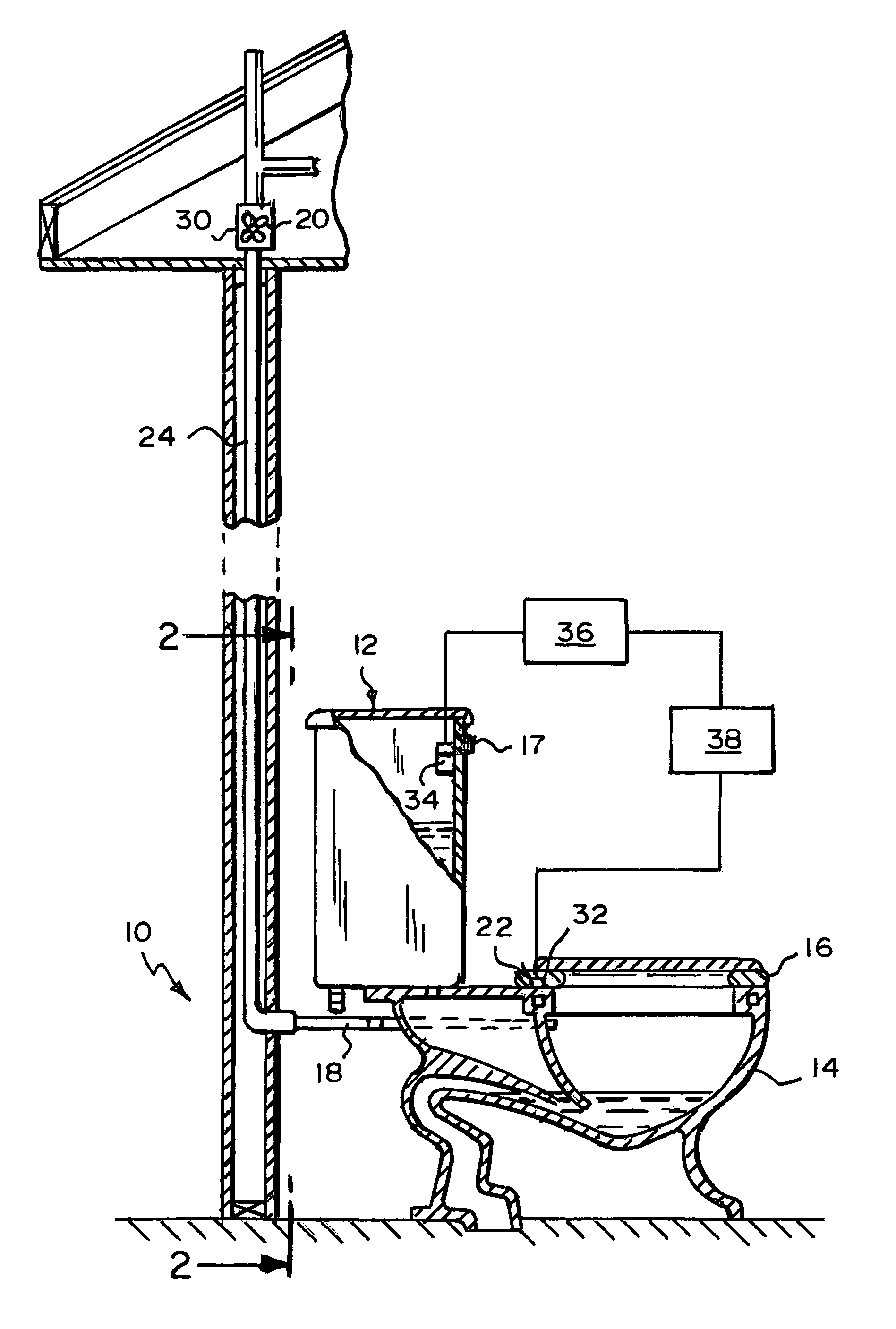
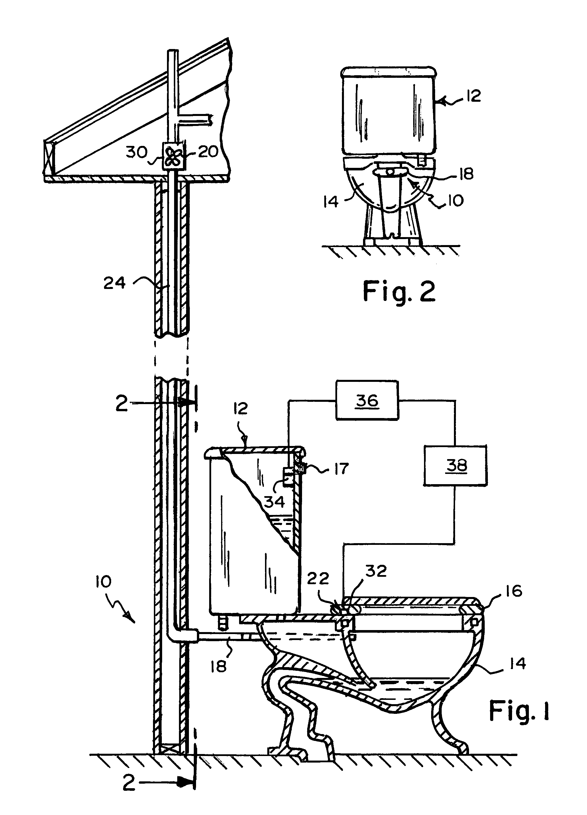
[0042]Referring now to the figures, in which like numerals indicate like parts, and particularly to FIGS. 1 and 2, the system of the present invention is shown generally at 10 for venting noxious fumes from a toilet 12. The toilet 12 has a bowl 14, a seat 16, and a flush handle 17.

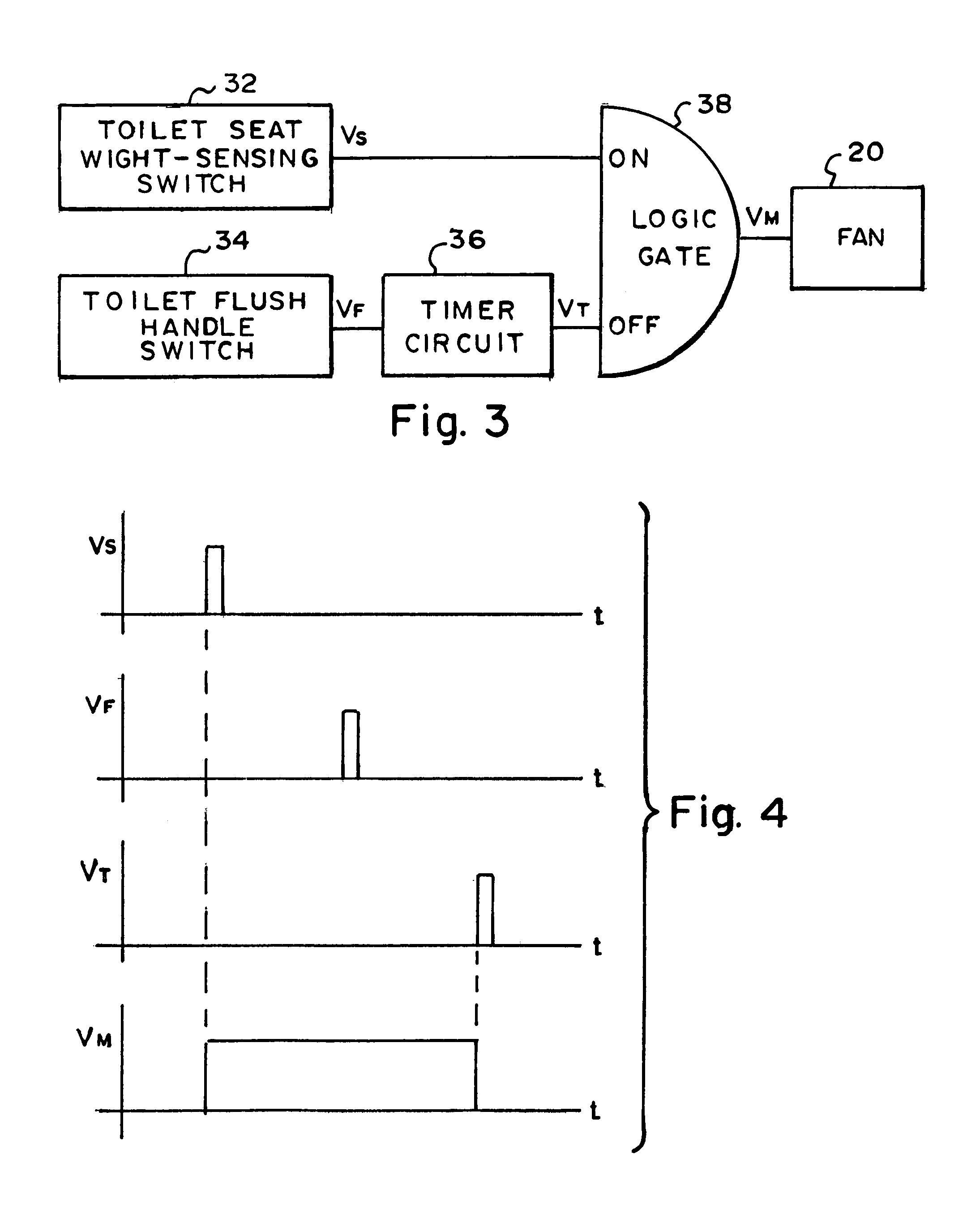
[0043]The system 10 comprises a conduit 18, a fan 20, and an activator 22. The conduit 18 is for communicating with the bowl 14 of the toilet 12. The fan 20 communicates with the conduit 18 and is for venting the noxious fumes from the toilet 12. The activator 22 is operatively connected to the fan 20.

[0044]The conduit 18 is generally Y-shaped and is for extending straddlingly rearwardly from the bowl 14 of the toilet 12.

[0045]The system 10 further comprises a vent stack 24. The vent stack 24 extends communicatingly from the conduit 18 and is for extending into the ambient.

[0046]The system 10 further comprises a housing 30. The housing 30 communicates with the vent stack 24 and contains the fan 20.

[0047]Th...


PUM


Abstract

A system for venting noxious fumes from a toilet. A toilet seat weight-sensing switch operatively connects to a fan and activates when the seat of the toilet is sat upon. A toilet flush handle switch activates when the flush handle of the toilet activates. A timer circuit activates when the toilet flush handle switch is activated. A logic gate operatively connects to the toilet seat weight-sensing switch, the timer circuit, and the fan. When the seat of the toilet is sat upon, the toilet seat weight-sensing switch generates a pulse turning on the logic gate which generates a pulse which turns on the fan. When the flush handle of the toilet activates, the toilet flush handle switch generates a pulse turning on the timer circuit which after a predetermined time generates a pulse which turns off the logic gate which turns off the fan.

Description

BACKGROUND OF THE INVENTION[0001]1. Field of the Invention[0002]The present invention relates to a toilet, more particularly, the present invention relates to a system for venting noxious fumes from a toilet.[0003]2. Description of the Prior Art[0004]Numerous innovations for vented toilets have been provided in the prior art that will be described. Even though these innovations may be suitable for the specific individual purposes to which they address, however, they differ from the present invention.[0005]A FIRST EXAMPLE, U.S. Pat. No. 2,997,935 to Baither teaches a ventilated toilet comprising a bowl having a water basin therein and a drainpipe below the basin and communicating therewith, means for creating a suction in the bowl above the water basin including an electric motor and a fan, a protecting housing for the motor and fan entirely enclosing the same and constituting a foul odor receiving chamber, means connecting the interior of the housing with the bowl, the inlet of the ...

Claims


Application Information

Patent Timeline
Patent Type & Authority Patents(United States)
IPC IPC(8): E03D9/04E03D9/052
CPCE03D9/052
Inventor CANALES, JR., AMADOR
Owner CANALES JR AMADOR
Why Eureka
Try Eureka