Roof deck and parapet structure

a technology of roof deck and parapet, applied in the direction of building roof, walls, snow traps, etc., can solve the problems of local stresses between roof components, wood blocking, and local stresses between roof and blocking materials, and achieve the effect of improving protection

Inactive Publication Date: 2005-09-20
LOADMASTER SYST
View PDF13 Cites 25 Cited by
  • Summary
  • Abstract
  • Description
  • Claims
  • Application Information

AI Technical Summary

Benefits of technology

[0006]To deal with these problems, there is need for improved protection from the stresses between the roo

Problems solved by technology

These diaphragm forces result in stress between roof components, especially at roof transition and termination points.
Such relative movement results in local stresses between the roofing and blocking materials and between the roof assembly and the roof support system.
Further problems aris

Method used


Image

  • Roof deck and parapet structure
  • Roof deck and parapet structure
  • Roof deck and parapet structure

Examples


Embodiment Construction

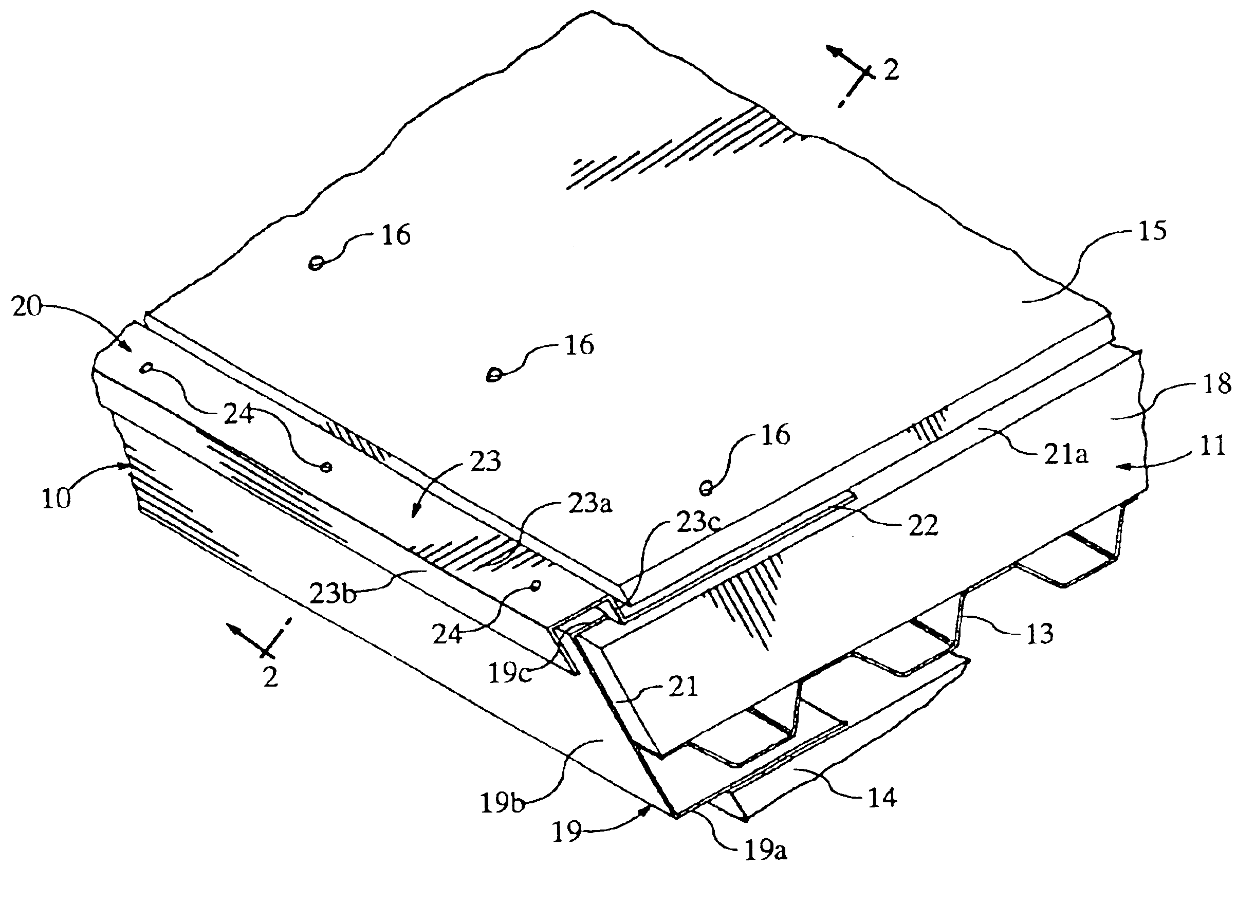
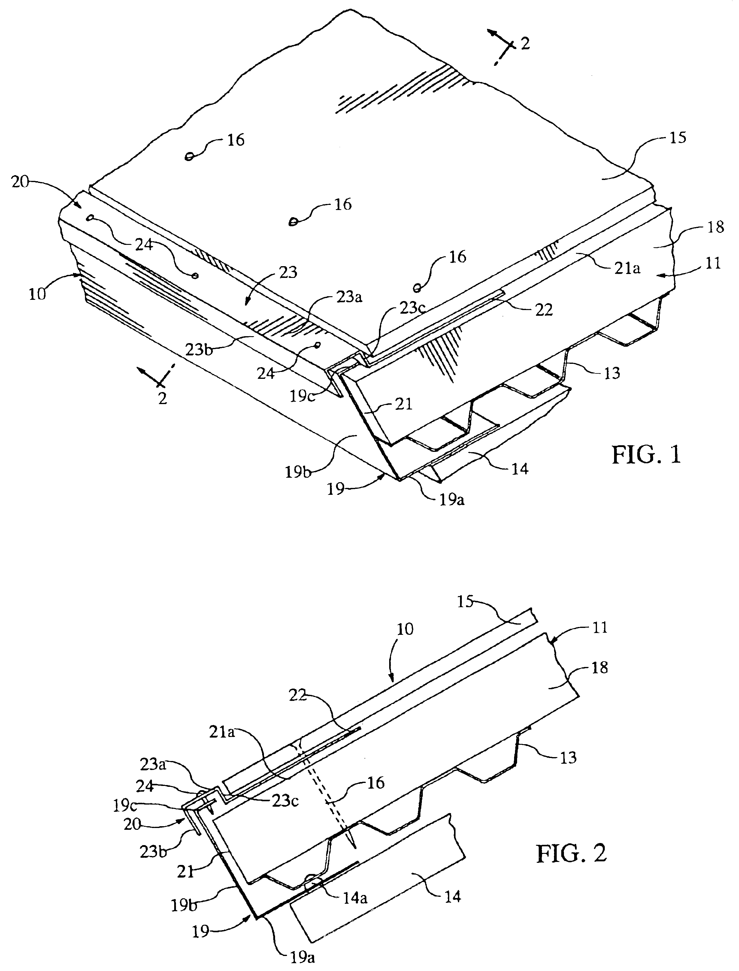
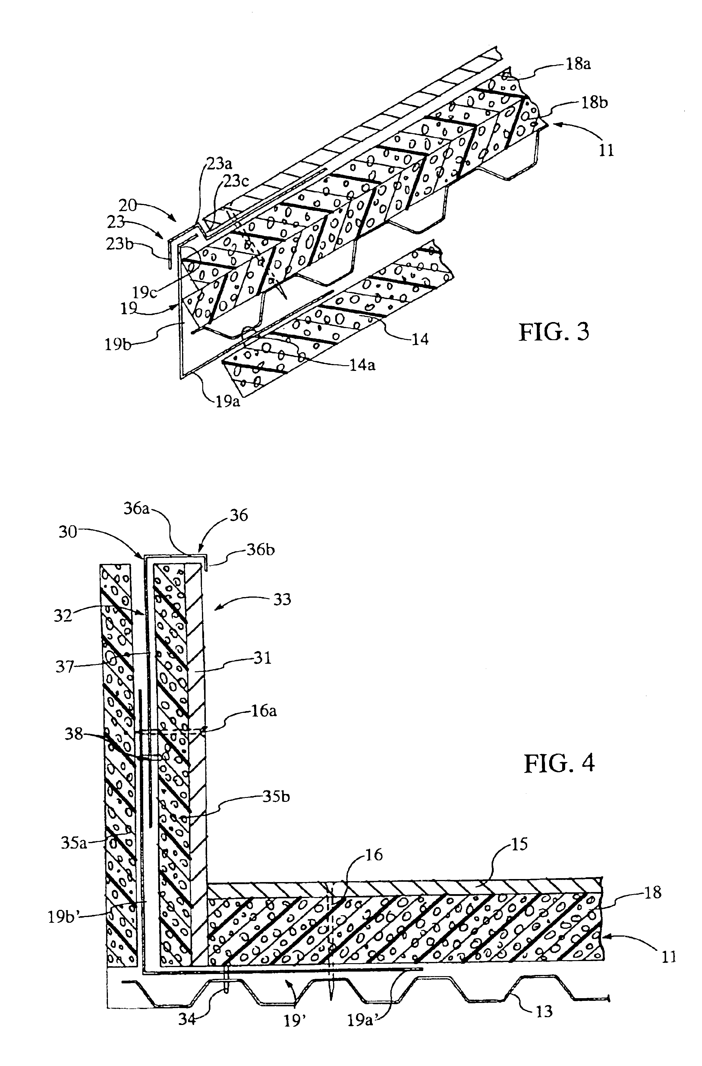
[0021]The roof perimeter and wall transition assemblies are designed to be a part of the roof deck and are fastened to the roof deck. The assembled components form structural units in conjunction with the roof deck and are designed to respond to the forces roof decks typically encounter. The components acting in concert with the roof deck, resist uplift and diaphragm forces and protect the roof deck with an overlap design that accommodates relative movement between adjoining roof decks and other roof structures, such as parapet walls. Terms such as “left,”“right,”“clockwise,”“counter-clockwise,”“horizontal,”“vertical,”“up” and “down” when used in reference to the drawings, generally refer to orientation of the parts in the illustrated embodiment and not necessarily during use. The terms used herein are meant only to refer to relative positions and / or orientations, for convenience, and are not to be understood to be in any manner otherwise limiting. Further, dimensions specified here...


PUM


Abstract

A roof transition assembly for a roof deck having a corrugated sheet and a rigid sheet wherein a base component is positioned at the perimeter of the roof deck and has two legs. The first leg secures the base component to the corrugated sheet, and the second leg extends from the first leg, generally parallel to a free edge of the roof deck. The second leg includes an anchoring surface. An upper component positioned at the perimeter of the roof deck has a connector portion and an anchor portion. The anchor portion is secured to the roof deck, and the connector portion extends from the anchor portion and overlays and is secured to the anchoring surface of the base component, thus anchoring the base component and upper component to the roof deck.

Description

CROSS-REFERENCE TO RELATED APPLICATIONS[0001]This application is a division Utility Application Ser. No. 09 / 614,016, filed Jul. 11, 2000, now U.S. Pat. No. 6,751,923, by C. Lynn Nunley entitled “ROOF DECK TERMINATION STRUCTURE,” which claims the benefit application of Provisional Application Ser. No. 60 / 043,522 filed Apr. 15, 1997 by C. Lynn Nunley entitled “ROOF DECK TERMINATION STRUCTURE,” now abandoned, the disclosures of which are incorporated herein by reference in their entirety for all purposes.FIELD OF THE INVENTION[0002]The present invention relates to improved roofing components. More particularly, this invention relates to transition assemblies for protecting and reducing the stresses at roof deck perimeters and parapet walls.BACKGROUND OF THE INVENTION[0003]Conventional roof deck design typically calls for wood blocking at the termination points of the roof deck assembly and at the transitions between multiple roof decks, such as expansion joints. The wood blocking is us...

Claims


Application Information

Patent Timeline
IPC IPC(8): E04D13/15E04D13/158
CPCE04D13/15E04D13/151E04D13/158
Inventor NUNLEY, C. LYNN
Owner LOADMASTER SYST
Why Eureka
Try Eureka