Sanitizable piston pumps and dispensing systems incorporating the same

a piston pump and sanitizer technology, applied in the direction of liquid transfer devices, instruments, volume meters, etc., can solve the problems of not being able to meet the requirements of the conventional piston pump and the conventional nutating pump have been used, and the system designed for non-sanitary products such as paint is not readily applicable to products that must be sanitary, etc., to achieve the effect of convenient dislodgmen

Inactive Publication Date: 2005-09-20
FLUID MANAGEMENT LLC
View PDF87 Cites 17 Cited by
  • Summary
  • Abstract
  • Description
  • Claims
  • Application Information

AI Technical Summary

Benefits of technology

[0012]Thus, the valve stem may be easily removed from the valve block and the cylinder may be easily removed from the valve block. Further, the piston may be easily removed from the cylinder and thereby the separated components may be easily cleaned and / or sanitized.
[0013]In a refinement, the proximal end of the cylinder is threadably connected to a lock nut which prevents the piston from exiting the proximal end of the cylinder.
[0014]In another refinement, the piston is connected to a distal end of a rod, which further comprises a proximal end that is threadably connected to a lock fastener. The lock fastener prevents the proximal end of the rod from entering the cylinder. The lock fastener also provides a surface or gripping element for an actuator to control movement of the piston.
[0021]In another refinement, a push bar and lever system is provided which enables flexible packages to be easily dislodged from the nipples of the piston pumps. Specifically, each female outlet of each packages passes through a horizontal flange. This flange is engaged to a lever which can be pivotally mounted to the valve block or to some other structure of the dispense system. The lever is also connected to a vertical rod. Downward pressure on the vertical rod causes pivotal movement of the lever against the annular flange to dislodge the female connector associated with the package from the nipple or male connector associated with the pump. A quick and easy dislodgment is provided by this system.

Problems solved by technology

However, such systems designed for non-sanitary products such as paint are not readily applicable to products that must be sanitary, such as cosmetics and foods.
However, unlike the mixing of paint, cosmetic products are applied directly to a customer's skin and therefore a certain degree of sanitization is required.
Thus, conventional piston pumps and conventional nutating pumps which have been used in the past for the formulation of paint, cannot be used in cosmetic application and other applications requiring a sanitary product because the pumps themselves are not designed to be frequently cleaned or sanitized.
Simply put, the time and labor involved in cleaning or sanitizing conventional piston or nutating pumps would render the operation of a dispensing system used to prepare customized cosmetic products at a point of sale too expensive to be practical.
One problem associated with the use of these connectors is the force required to remove a package from a pump once the male-female connection is made.
Employees or technicians operating a multiple dispensing system with flexible packages having these types of connectors often struggle to replace an empty package or simply change packages.

Method used


Image

  • Sanitizable piston pumps and dispensing systems incorporating the same
  • Sanitizable piston pumps and dispensing systems incorporating the same
  • Sanitizable piston pumps and dispensing systems incorporating the same

Examples


Embodiment Construction

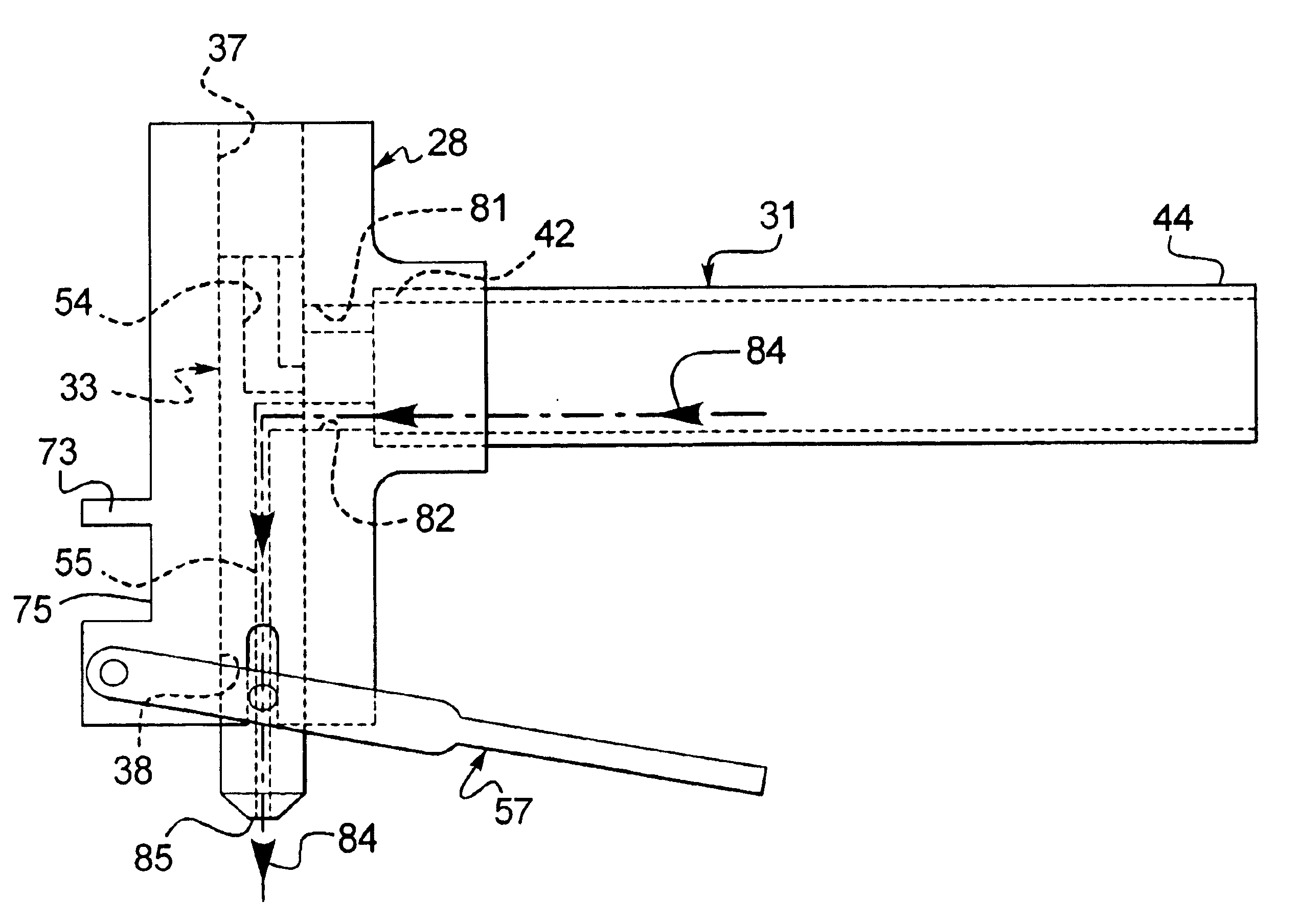
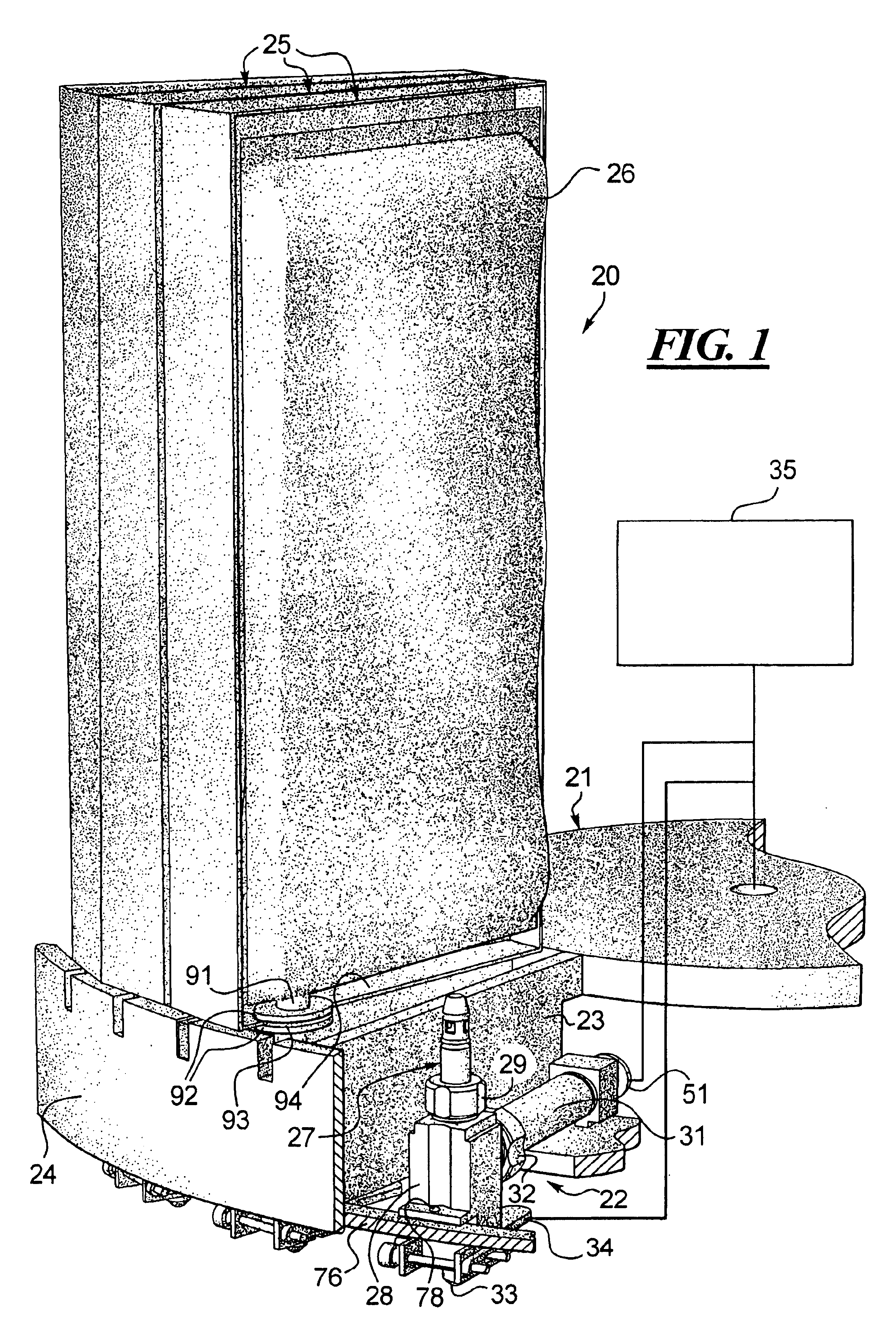
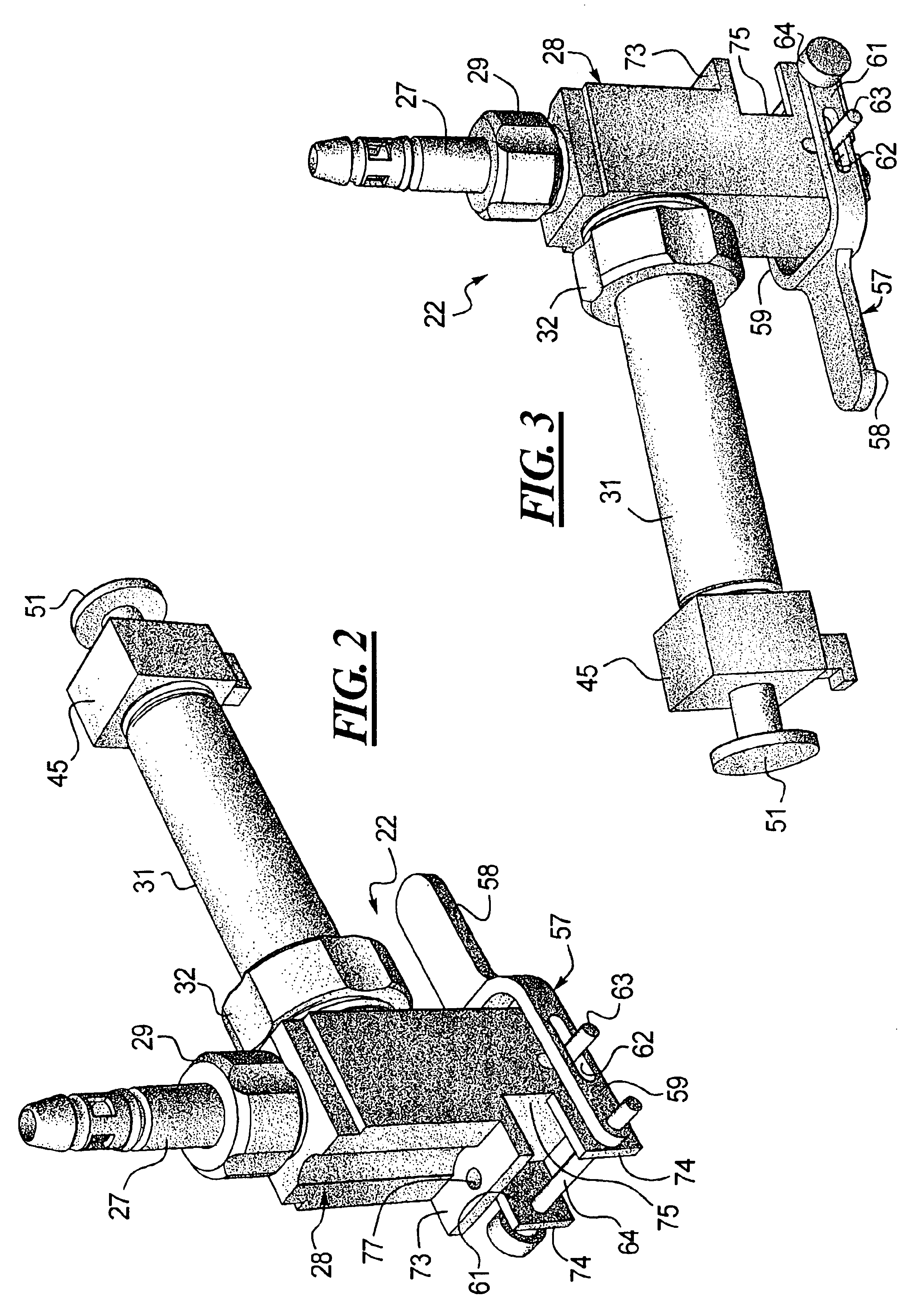
[0034]Turning to FIG. 1, a dispensing system 20 is disclosed which includes a rotary turntable 21 on which a plurality of pumps 22 are mounted. The pumps 22 are mounted between sectional walls shown at 23 and inside of a outer circumferential wall 24 which, in turn, support a plurality of frames 25 that support the flexible ingredient packages, one of which is shown at 26. The connection between each flexible package 26 and each pump 22 is made primarily by way of the nipple or inlet port 27 of the piston pump 22 which serves as a male connection and is received in a female outlet port (not shown) disposed in the flexible package 26. The nipple 27 is detachably connected to the valve block 28 by the threaded connection shown at 29.

[0035]Also connected to the valve block 28 is a cylinder 31 which slidably receives a piston (not shown). The cylinder 31 is also threadably connected to the valve block 28 by way of the threaded connector 32. A rod (not shown in FIG. 1) is connected to a ...


PUM


Abstract

A sanitizable piston pump for dispensing ingredients of cosmetic preparations and other sanitary mixtures is shown and described. The pump includes a valve block including an inlet port threadably connected to a nipple which is detachably connected to an outlet port of a flexible package. The valve block further includes a piston port threadably connected to cylinder and an outlet port that sealably receives a valve stem. The inlet port, the outlet port and the piston port are in fluid communication with one another upon removal of the valve stem from the valve block. The valve stem includes an intake passage and an output passage. The cylinder slidably receives a piston. Both the piston and valve stem are connected to separate actuators. The actuator connected to the valve stem moves the valve stem into one of either an intake position for withdrawing fluid into the cylinder or a dispense position for pumping fluid out of the cylinder and out the outlet of the valve stem. A disposable plastic piston pump is also disclosed. Further, a lever mechanism for quickly and easily releasing a flexible package from the nipple connected to the valve block of the disclosed piston pumps is also shown and described.

Description

TECHNICAL FIELD[0001]Piston pumps for dispensing systems used in the preparation of sanitary products, such a cosmetics, are disclosed. More specifically, a piston pump that may be easily disassembled and sanitized and which can be incorporated into a complex dispensing system is disclosed. Further, a disposable plastic piston pump for use in such a complex dispensing system is also disclosed. Finally, improvements to dispensing systems that include multiple pumps dispensing multiple ingredients or components are disclosed which include improved mechanisms for removing or detaching flexible ingredient packages from piston pumps and improved drip catcher and container holders for small containers, such as small glass or plastic containers used to hold cosmetic products, are also disclosed.DESCRIPTION OF THE RELATED ART[0002]Multiple pump dispensing systems have been used in the paint industry. Specifically, such a dispensing system incorporating multiple pumps dispensing viscous flui...

Claims


Application Information

Patent Timeline
Patent Type & Authority Patents(United States)
IPC IPC(8): A47K5/00A47K5/12
CPCA47K5/1204B01F33/841
Inventor MILLER, WILLIAM A.
Owner FLUID MANAGEMENT LLC
Why Eureka
Try Eureka