
Printer, printer system, printer control method, and program therefor

a printer and control method technology, applied in the field of printers, can solve the problems of deterioration of the quality of printed materials, difficult reprinting via a network such as a lan (local area network), and other general purpose devices cannot be used, so as to prevent the duplication of identification numbers between documents and between devices

Inactive Publication Date: 2005-09-20
FUJIFILM BUSINESS INNOVATION CORP
View PDF15 Cites 16 Cited by
  • Summary
  • Abstract
  • Description
  • Claims
  • Application Information

AI Technical Summary

Benefits of technology

[0014]Therefore, an object of the present invention is to provide a printer for reducing the troublesome work involved in obtaining duplicates of printed material by means of a general-purpose device, as well as a printer system, a printer control method, and a program thereof.
[0015]Further, another object of the present invention is to provide a printer for performing document management of and retrieval of printed material easily by means of a printer that prints electronic data via a client, as well as a printer system, a printer control method and a program thereof.
[0016]Yet another object of the present invention is to provide a printer that performs document management of received electronic data and renders a document search straightforward, as well as a printer system, a printer control method, and a program thereof.

Problems solved by technology

However, a method that optically reads and duplicates the printed material results in a deterioration of the quality of the printed material.
The document creator who has been asked to perform printing is required to carry out a troublesome task that involves searching for the document file, running an application to open and print the document file, and passing the printed document copy(ies) to the party requesting the copies.
The method in (2) employs a special device for filing documents (a word processor, electronic file copier), and, because this method is restricted to usage of a special device, other general purpose devices cannot be used.
For example, when the party requesting the copies other than the document creator uses a general-purpose personal computer, it is difficult to perform reprinting via a network such as a LAN (Local Area Network).
In addition, when printing is performed, there is then the troublesome labor of downloading data in the server to the client, and running an application to open and print the document file.
More particularly, in the case of an application where the format of the original document is not installed on his or her own personal computer, there are costs and labor involved in purchasing and installing the application, and so forth.

Method used


Image

  • Printer, printer system, printer control method, and program therefor
  • Printer, printer system, printer control method, and program therefor
  • Printer, printer system, printer control method, and program therefor

Examples


first embodiment

[0061][First Embodiment]

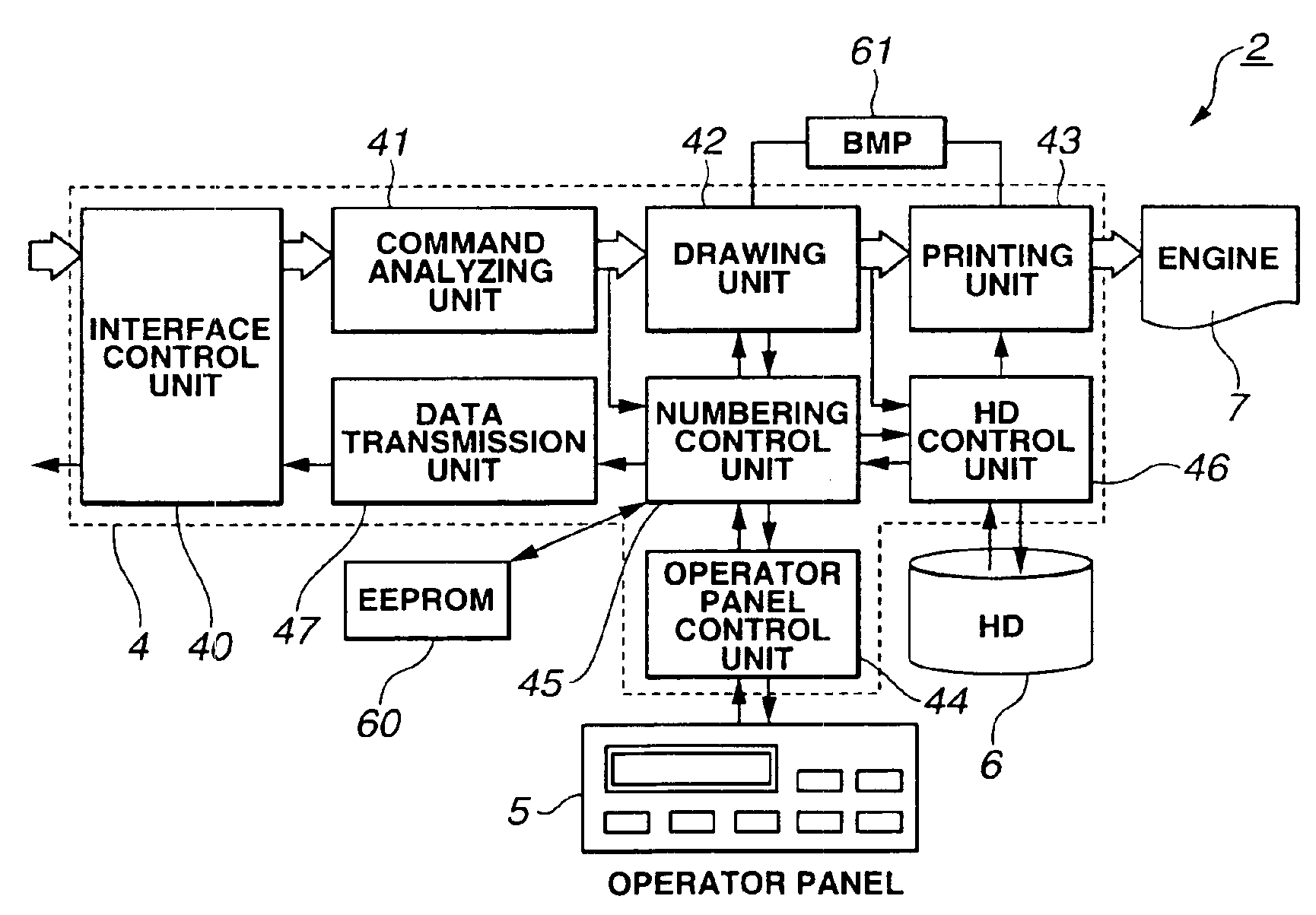
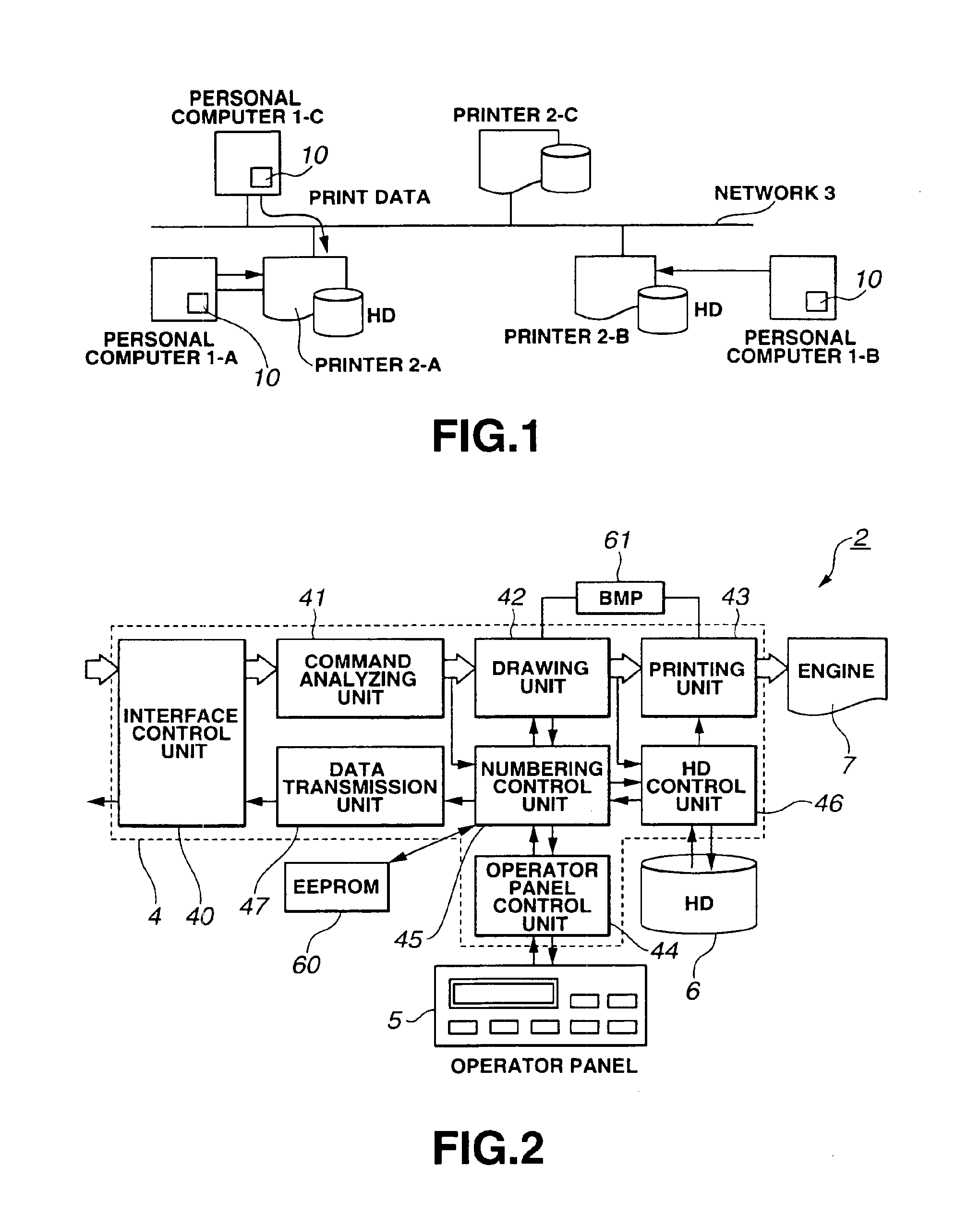
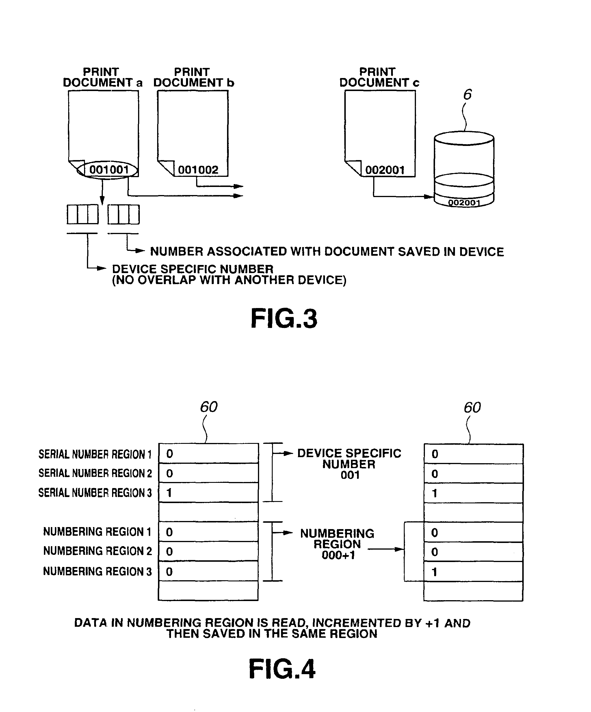
[0062]FIG. 1 is a constitutional view of the printer system of the first embodiment of the present invention; FIG. 2 is a block diagram of the printer in FIG. 1; FIG. 3 is an explanatory view of the document management of the printer in FIG. 1; FIG. 4 is an explanatory view of the document management number of the printer in FIG. 1; FIG. 5 is an explanatory view of the printer driver that designates the document management of the printer by means of the personal computer in FIG. 1; and FIG. 6 is an explanatory view of the operator panel of the printer in FIG. 1.

[0063]As shown in FIG. 1, a personal computer (PC) 1-C, and printers 2-A, 2-B, and 2-C are connected to a network 3 such as a LAN (Local Area Network). Further, personal computers 1-A and 1-B are connected to the printers 2-A and 2-B.

[0064]The personal computer 1-C is able to use any of the three printers 2-A, 2-B, and 2-C via the network 3. The personal computers 1-A and 1-B are able to use the printe...

second embodiment

[0132][Second Embodiment]

[0133]Next, an embodiment that uses a WAN (Wide Area Network) as the abovementioned network 3 will be described. FIG. 14 is a system constitutional view of the second embodiment of the present invention. FIG. 15 is a constitutional view of the interface in FIG. 14. FIG. 16 is an explanatory view of the operation of the system in FIG. 14. In these figures, those parts which are the same as those shown in FIGS. 1 and 2 are shown with the same reference symbols.

[0134]In FIG. 14, the printers 2-A and 2-B are connected to a personal computer 1-C and a Web client terminal 1-D via a WAN 3-a. The WAN 3-a comprises the LAN described above.

[0135]The printers 2-A and 2-B comprise a network communication function (processing) unit 4-a that provides network communications with the other devices 1-C, 1-D, and 2-B and so forth via the WAN 3-a; a document management function (processing) unit 4-C that performs the abovementioned document management; a Web server function (p...

third embodiment

[0160][Third Embodiment]

[0161]Next, an embodiment for a case where the printer does not comprise the HDD 6, which constitutes a modified example of the second embodiment, will be described. FIG. 24 is a constitutional view of the system of the third embodiment of the present invention. FIG. 25 is a flowchart for the print processing of FIG. 24; FIG. 26 is a flowchart for the reprint processing of FIG. 24; and FIG. 27 is a flowchart for the document transmission processing of FIG. 24. FIG. 28 is an explanatory view of the operation of the system in FIG. 24. In these figures, those parts which are the same as those shown in FIGS. 1, 2, and 14 are shown with the same reference symbols.

[0162]In FIG. 24, the printers 2-A and 2-B are connected to and managed by a management server 21. Each management server 21 is connected to a personal computer 1-C and a Web client terminal 1-D via the WAN 3-a. This WAN 3-a contains the abovementioned LAN.

[0163]The management server 21 acts as a print se...


PUM


Abstract

A controller (4) for controlling a printer engine (7) used to print data on a medium determines an identification number based on received data, and prints the identification number together with print data based on the received data on the medium. Simultaneously, the controller (4) stores therein the identification number and the print data in an HD (6). With the construction, the identification number printed on the medium is inputted in the next and later printing operations. The controller (4) searches the HD (6) to retrieve and print the print data. Therefore, a copy of a quality as high as that of the original document can be produced.

Description

TECHNICAL FIELD[0001]The present invention relates to a printer that performs management and retrieval of printed documents, to a printer system, printer control method, and program therefor, and, more particularly, to a printer for facilitating document re-printing, a printer system, a printer control method, and a program therefor.BACKGROUND ART[0002]Printers that receive computer electronic data and print same on a sheet are widely used as computer output devices. Sometimes printed material that has been printed by such printers is viewed and then the printed material on hand is duplicated. Generally, a method that involves duplicating the printed material by means of a photocopier is used. However, a method that optically reads and duplicates the printed material results in a deterioration of the quality of the printed material. This tendency becomes more prominent as the number of copies of the same printed material increases.[0003]For this reason, a method that involves obtain...

Claims


Application Information

Patent Timeline
IPC IPC(8): B41J29/393G06F21/60
CPCB41J29/393G06F21/608
Inventor HATA, HISAOWATANABE, HIROTAKE
Owner FUJIFILM BUSINESS INNOVATION CORP
Learn More