
Wind power generation system

a wind power generation and wind power technology, applied in the direction of wind energy generation, liquid fuel engine components, optimise machine performance, etc., can solve the problems of inability to achieve improvement in the performance of the wind power generator itself and in the whole system, and the mechanical innovation of the wind power generator is not always easy, so as to accurately smooth (stabilize) the output amount, the effect of stabilizing the supply of electric power and suppressing the fluctuation of outpu

Active Publication Date: 2005-09-20
MITSUBISHI ELECTRIC CORP
View PDF7 Cites 111 Cited by
  • Summary
  • Abstract
  • Description
  • Claims
  • Application Information

AI Technical Summary

Benefits of technology

The present invention aims to solve problems in wind power generation by providing a system that can predict the direction and velocity of wind and control the wind power generator accordingly to achieve high efficiency operation and stable output. The invention includes a wind power generator and a laser aerovane that observes the wind direction and velocity, and the system can adjust the output of the wind power generator based on the observation results or calculate the output adjustment amount in advance and control the output accordingly. This allows for accurate suppression of fluctuations in output and stabilization of the overall wind power generation system.

Problems solved by technology

Hence a problem exists in that it is impossible to achieve improvement in performance of the wind power generator itself and in efficiency of the whole system.
Hence a problem exists in that it is impossible to achieve improvement in performance of the wind power generator itself.
However, mechanical innovation in the wind power generator is not always easy due to its simple structure.

Method used


Image

  • Wind power generation system
  • Wind power generation system
  • Wind power generation system

Examples


embodiment 1

[0029]Embodiment 1 of the invention is hereinafter described with reference to FIGS. 1 to 6.

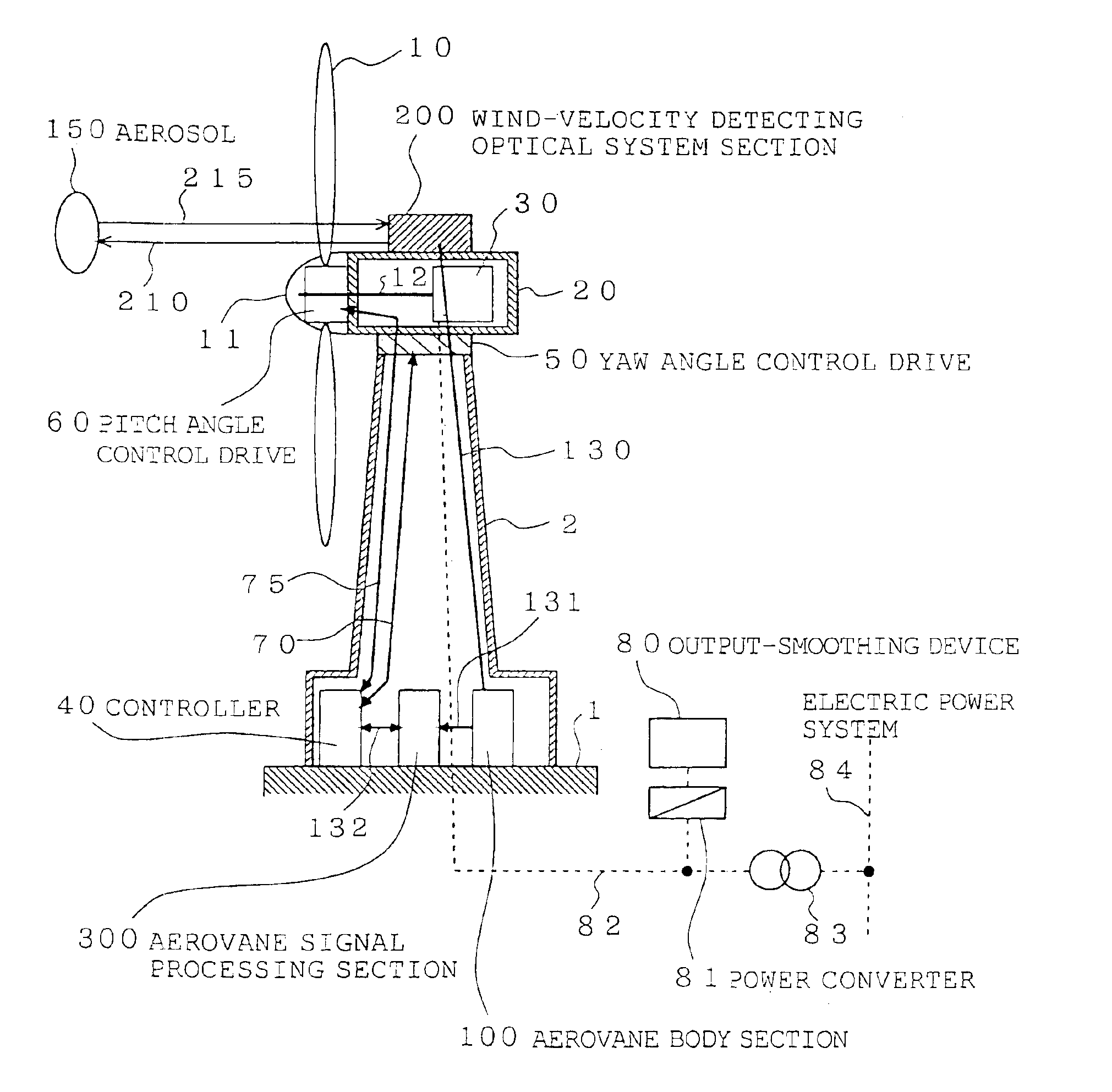
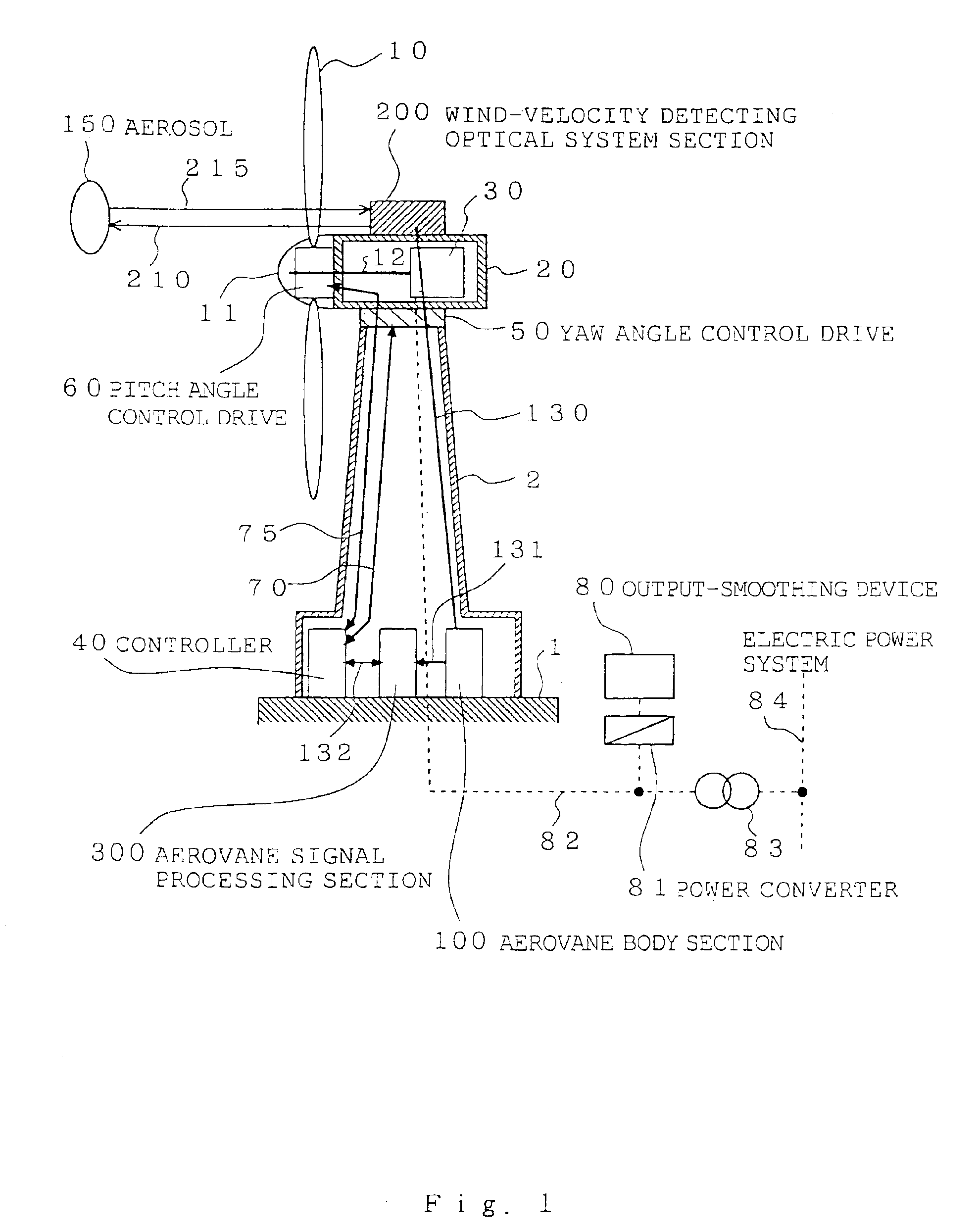
[0030]FIG. 1 is a sectional side view of a wind power generator (a windmill). As shown in FIG. 1, a tower section 2 is built on a pedestal 1, and a yaw angle control drive 50 is mounted on the top of the tower section 2. Furthermore, a nacelle 20 controlled so as to rotate within a horizontal plane by driving the yaw angle control drive 50 is mounted on the top of the yaw angle control drive 50. It is desirable to control the windmill so that plane where a propeller of the windmill rotates is changed conforming to change in direction of wind and catches the wind right in front at all times. It is yaw angle that is changed at this time, and controlling the yaw angle is called yaw control. Rotating the nacelle 20 within a horizontal plane can change the yaw angle.

[0031]Blades 10 constituting a propeller of the propeller-type windmill are mounted on a rotary shaft 12 through a hub (the portion o...

embodiment 2

[0088]Embodiment 2 of the invention is hereinafter described below with reference to FIG. 7. FIG. 7 is a schematic view of constitution of a wind farm provided with plural wind power generators 610a to 610c. FIG. 7 shows a state that an optical system section 200 (corresponding to the wind-velocity detecting optical system section) of the laser aerovane arranged in the middle of the wind farm. A tower section (pole) 601 is built in the middle of the plural wind power generators 610a to 610c, and the optical system section 200 is mounted on the tower section 601 through an optical system section yaw angle control drive 602 (hereinafter referred to as drive). The optical system section 200 is connected to the main body section 100 through an optical fiber 130a. The main body section 100 and the signal processing section 300 are connected through a communication system section 131a. The signal processing section 300 is connected to controllers 40a to 40c of the wind power generators th...

embodiment 3

[0098]The foregoing Embodiments 1 and 2 describe control examples in which rotation energy of the wind power generation system is converted into electrical energy, i.e., generated electric power is transmitted as it is to the system. In this Embodiment 3, a system arranged by combining the wind power generator, the laser aerovane, and the output-smoothing device together is employed as a wind power generation system. In this invention, an output adjustment amount of the wind power generator is calculated in advance on the basis of the wind-state prediction data obtained by the laser aerovane, and then on the basis of the calculated conditions, the output-smoothing device stores dump power otherwise releases stored energy when electric power generated by the wind power is insufficient. The same output-smoothing device is operated so that fluctuation is suppressed up to a level at which the existing power generation system of the system can follow, and the generated power of the whole...


PUM


Abstract

A wind power generation system capable of outputting generated power at high efficiency with a smoothed output power includes a wind power generator and a laser aerovane mounted on the wind power generator or located near the wind power generator. Direction and velocity of wind blowing toward the wind power generator are observed using the laser aerovane, and a yaw angle and / or a pitch angle of the wind power generator is predicted and controlled based on the observation results. Thus, high-efficiency control of the wind power generation system, including the wind power generator, is achieved. An output-smoothing device connected to the wind power generator predicts and controls electric power input / output of the output-smoothing device based on a predicted power output of the wind power generator and smoothes the power output of the wind power generation system.

Description

BACKGROUND OF THE INVENTION[0001]1. Field of the Invention[0002]The present invention relates to a wind power generation system for observing in advance a state of wind ahead of a wind power generator and high-efficiency operation control of the wind power generator or controlling and smoothing output of the whole system including the wind power generator.[0003]2. Description of the Related Art[0004]In one of conventional wind power generation systems for predicting a state of wind, a wind vector ahead of the wind power generator is measured with the use of a Doppler radar utilizing radio wave, an output value of the wind power generator is predicted on the basis of the wind vector, and output control of the electric power system side generator is carried out on the basis of the predicted output value (see the Japanese Patent Publication (unexamined) No. 2002-152975, for example).[0005]In another conventional system, a combination of a wind power generator and a Diesel-engine genera...

Claims


Application Information

Patent Timeline
Patent Type & Authority Patents(United States)
IPC IPC(8): F03D11/00F03D7/04F03D9/00F03D9/02H02J3/38H02P9/00
CPCF03D7/0204F03D7/0224F03D7/028F03D7/042F05B2260/80F05B2260/821F05B2270/20F05B2270/32F05B2270/321F05B2270/805Y02E10/723Y02E10/725Y02E10/72Y02P80/10
Inventor YOSHIDA, YASUOJIMBO, HIROSHIEGAMI, TAKATOSHIHIRANO, YOSHIHITOANDO, TOSHIYUKINAKAYAMA, HITOSHI
Owner MITSUBISHI ELECTRIC CORP
Learn More