
Pole winding pattern having parallel wound paths

a winding pattern and parallel technology, applied in the field of windings, can solve the problems of inability to achieve the ratio of voltage to current by windings, the inability to finely adjust the voltage-holding turns count, and the inability to provide more than one path. the effect of improving the operating performan

Inactive Publication Date: 2005-09-20
SIEMENS AG
View PDF35 Cites 16 Cited by
  • Summary
  • Abstract
  • Description
  • Claims
  • Application Information

AI Technical Summary

Benefits of technology

[0018]As at least one pole is wound by at least two paths, these paths jointly wind at least one sub-area of the magnetic circuit. Asymmetries (e.g. rotor eccentricities) affecting said sub-area have the same effect on both paths, so that no circulating currents between the paths result from said asymmetries. The more paths are simultaneously involved in winding of many poles as possible, the less any asymmetries will cause circulating currents between the paths. There is therefore no disadvantage in providing more than a single path per phase.
[0066]Preferably the number of slots per pole per phase of the winding is a positive integer. In the case of a rotating field winding, this is an integral-slot winding. In comparison to a fractional-slot winding, i.e. a winding with a fractional number of slots per pole per phase, the air-gap field of a rotating field integral-slot winding generally has fewer harmonics. The result is generally an improved operating performance.

Problems solved by technology

Moreover, it is generally disadvantageous to provide more than one path, as lossy circulating currents between the paths are produced in the event of asymmetries in the motor (e.g. rotor eccentricities) if there are a plurality of paths.
Fine adjustment of the voltage-holding turns count and therefore of the ratio of voltage to current by the winding cannot be achieved in this way.

Method used


Image

  • Pole winding pattern having parallel wound paths
  • Pole winding pattern having parallel wound paths
  • Pole winding pattern having parallel wound paths

Examples


first embodiment

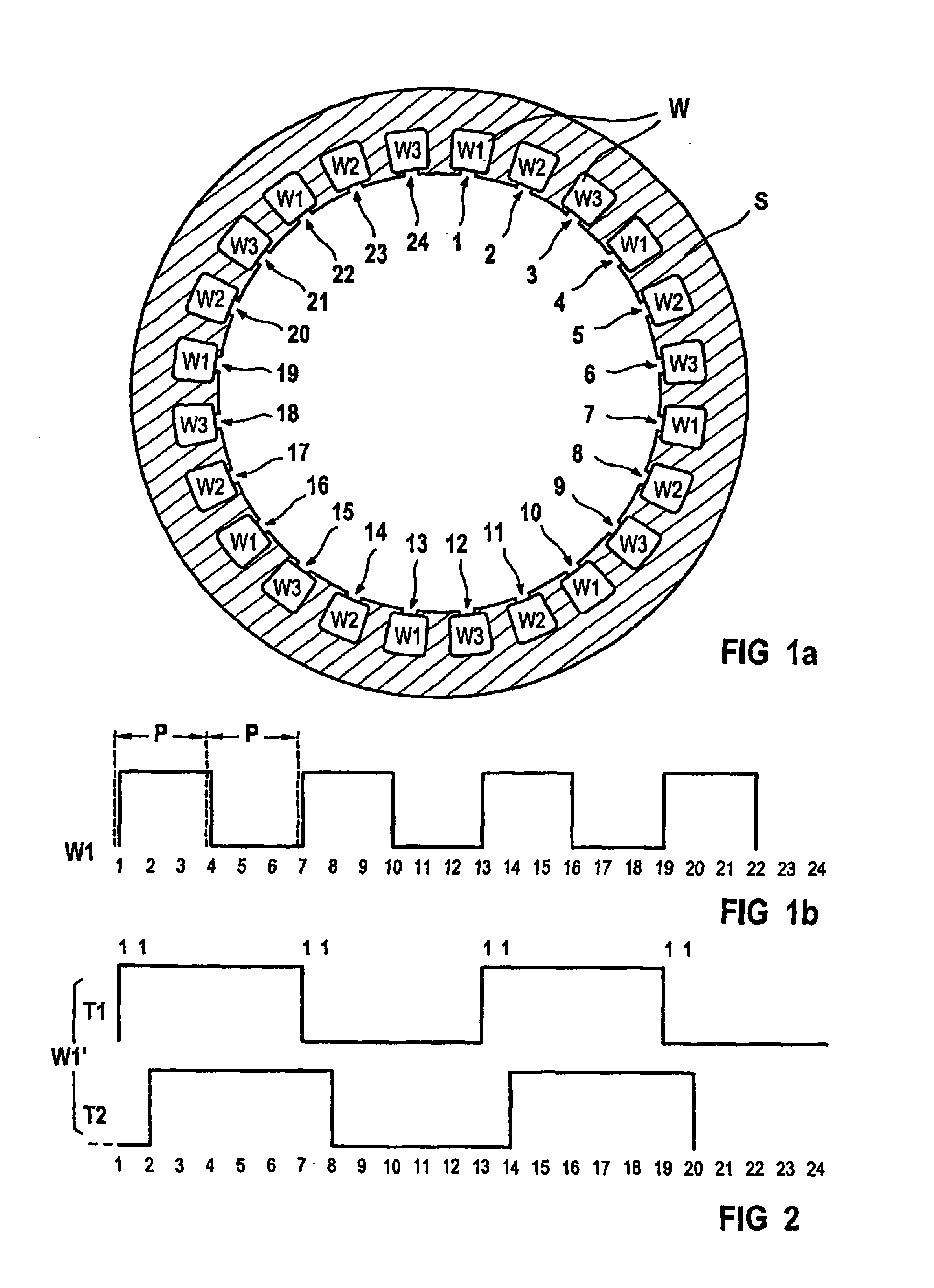
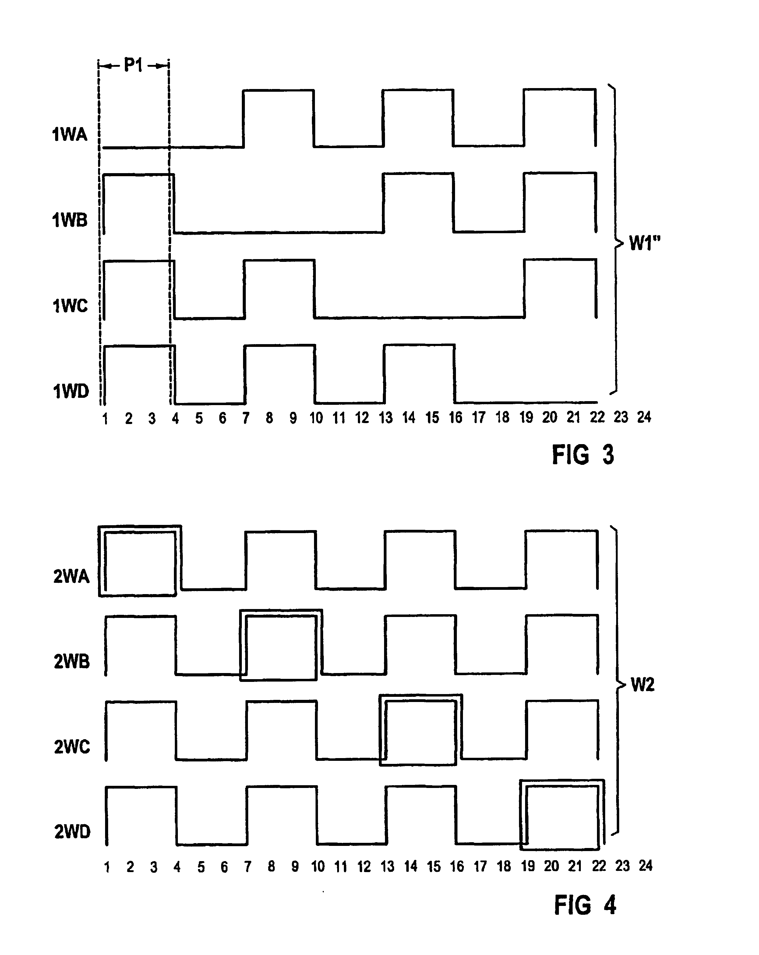
[0085]In a first embodiment, there is provided a first winding W1″ with three phases, each phase having four parallel paths 1WA, 1WB, 1WC, 1WD (see FIG. 3). Therefore, a=4. Only one of the three phases is shown in FIG. 3.

[0086]The paths 1WA, 1WB, 1WC, 1WD are implemented as wave windings. The first winding W1″ has 24 slots 1, . . . 24.

[0087]The first path 1WA runs along the slots 7, 10, 13, 16, 19, 22. The sections of the first path 1WA laid in the slots are interconnected by end connectors running outside the slots. In FIG. 3 the end connectors run horizontally, whereas the sections in the slots run vertically.

[0088]The first winding W1″ has a total of eight poles each wound by three of the four paths 1WA, 1WB, 1WC, 1WD. Therefore, p=4. A pole is formed by a slot wound by the phase and the end connector extending to the right to the next slot wound by the phase. Therefore, q=1. In FIG. 3, the region of the first pole P1 is shown schematically for the phase illustrated.

[0089]The eig...

second embodiment

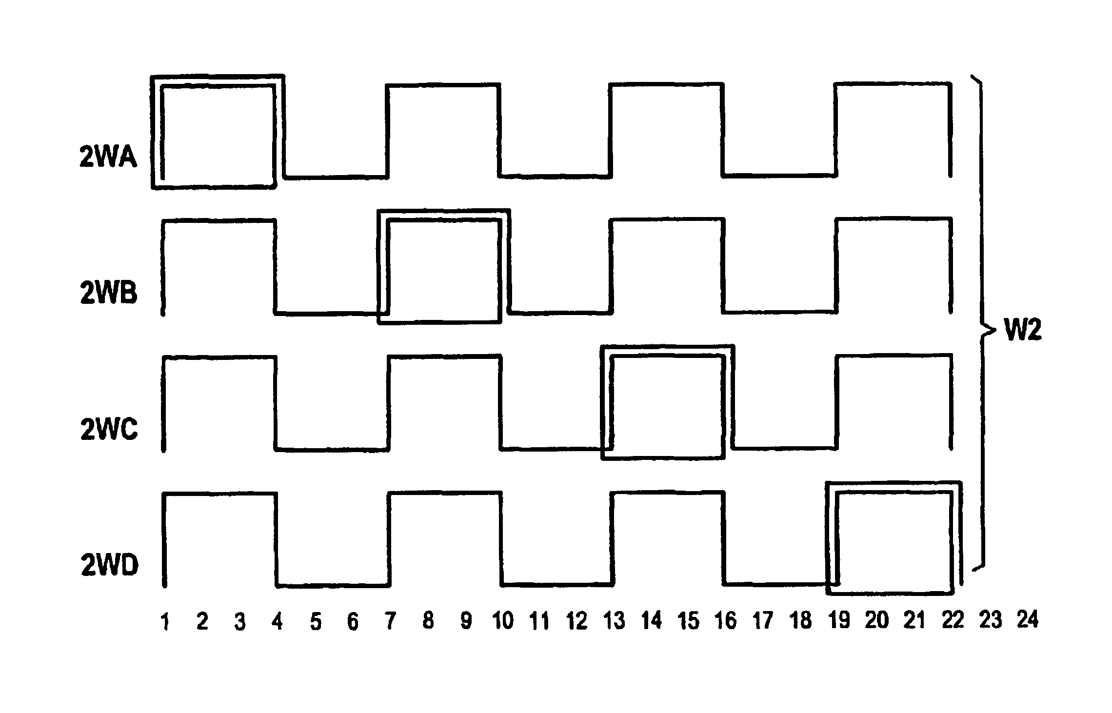
[0094]In a second embodiment there is provided a second winding W2 having three phases, each phase being formed from four parallel paths 2WA, 2WB, 2WC, 2WD (see FIG. 4). Consequently, a=4. Only one of the three phases is shown in FIG. 4.

[0095]As in the first embodiment, the second winding W2 has eight poles forming four pole pairs, i.e. p=4.

[0096]In contrast to the first embodiment, each path 2WA, 2WB, 2WC, 2WD has an additional turn, the additional turns being evenly distributed over the pole pairs so that each pole pair is wound by five turns. Five conductors are disposed in each slot, so that zN=5. Once again each pole is formed by a slot and the right-extending end connectors adjacent thereto, i.e. a pole is formed by one slot coil. Consequently, q=1.

[0097]The voltage-holding turns count of the second winding W2 is given by: w2=4×1×54=5

[0098]The additional turns are implemented in the manner of a lap winding. This ensures that the four paths 2WA, 2WB, 2WC, 2WD begin and end at t...

third embodiment

[0099]In a third embodiment there is provided a third winding W3 comprising three phases, each phase having eight parallel paths 3WA, 3WB, 3WC, 3WD, 3WE, 3WF, 3WG, 3WH (see FIG. 5). Therefore, a=8. Only one of the three phases is shown in FIG. 5.

[0100]The third winding W3 has 8 poles and 24 slots 1, . . . 24. Therefore, p=4.

[0101]Each of the paths does not wind two adjacent poles. Each path omits to wind a different pair of poles from the remaining paths.

[0102]The first path 3WA, the third path 3WC, the fifth path 3WE and the seventh path 3WG correspond to the paths 1WA, 1WB, 1WC, 1WD of the first embodiment. The second path 3WB corresponds to the mirror image of the first path 3WA about the winding axis, said path having been shifted one pole to the right. This applies correspondingly to the fourth path 3WD, the sixth path 3WF and the eighth path 3WH.

[0103]Each pole is therefore not wound by two paths. For example, the first pole is not wound by the first path 3WA and the eighth pa...


PUM


Abstract

The winding (W1) comprises at least two poles and at least one phase, with which the poles are wound. The phase comprises at least two parallel-wired winding branches (1WA, 1WB, 1WC, 1WD). At least two of the winding branches (1WA, 1WB) are different from each other in the winding of at least one of the poles (P1). At least one pole (P1) is wound from at least two winding branches (1WB, 1WC, 1WD). At least one of the winding branches (1WA, 1WB, 1WC, 1WD) is included in the winding of at least two poles. The poles are wound with the winding branches (1WA, 1WB, 1WC, 1WD) in the sense of an essentially symmetrical current loading of the phase.

Description

CROSS REFERENCE TO RELATED APPLICATION[0001]This application is a continuation of copending International Application No. PCT / DE / 02 / 01922 filed May 24, 2002, which designates the United States, and claims priority to German application number 10127364.9 filed Jun. 6, 2001.TECHNICAL FIELD OF THE INVENTION[0002]The invention relates to a winding.BACKGROUND OF THE INVENTION[0003]Current-carrying windings are used to generate magnetic fields. In particular, they can be used for electromagnetic energy conversion. For example, electric energy can be converted to mechanical energy by means of a winding (electromotive principle). If the winding is employed in a transformer, the winding serves to convert electric energy into electric energy.[0004]The amount of electromagnetically converted power is governed by the product of the voltage across the winding and the current flowing through the winding. For motor operation, the voltage and current are generally subject to certain constraints. Fo...

Claims


Application Information

Patent Timeline
Patent Type & Authority Patents(United States)
IPC IPC(8): H02K3/28
CPCH02K3/28
Inventor KRUSE, RALF
Owner SIEMENS AG
Learn More