Apparatus and methods for radome depolarization compensation

a technology of radome depolarization and apparatus, applied in the field of antenna systems, can solve the problems of increasing transmission loss, radome weight and cost, depolarization of electromagnetic waves passing through, etc., and achieve the effect of substantially reducing or eliminating the effect of radome depolarization in the transmitting and/or receiving mod

Inactive Publication Date: 2005-09-20
THE BOEING CO
View PDF15 Cites 39 Cited by
  • Summary
  • Abstract
  • Description
  • Claims
  • Application Information

AI Technical Summary

Benefits of technology

[0009]When an embodiment of the present invention is implemented, effects of radome depolarization in transmit and / or receive modes can be substantially reduced or eliminated.

Problems solved by technology

Radomes, however, tend to cause depolarization of electromagnetic waves passing through them at oblique incidence.
Studies have shown, however, that such improvements have only limited effect and may increase transmission loss, radome weight and costs.

Method used


Image

  • Apparatus and methods for radome depolarization compensation
  • Apparatus and methods for radome depolarization compensation
  • Apparatus and methods for radome depolarization compensation

Examples


Embodiment Construction

[0021]The following description of embodiments of the present invention is merely exemplary in nature and is in no way intended to limit the invention, its application, or uses. Although embodiments of the present invention are described herein in connection with an aircraft antenna system, it should be noted that the invention is not so limited. The present invention can be practiced in connection with radome-enclosed antenna systems on other platforms, for example, ships and ground vehicles. Embodiments also are contemplated relating to fixed ground-based antenna systems. It also should be noted that the present invention can be practiced in connection with a plurality of antenna types, including but not limited to array antennas, reflector antennas, and / or lenses.

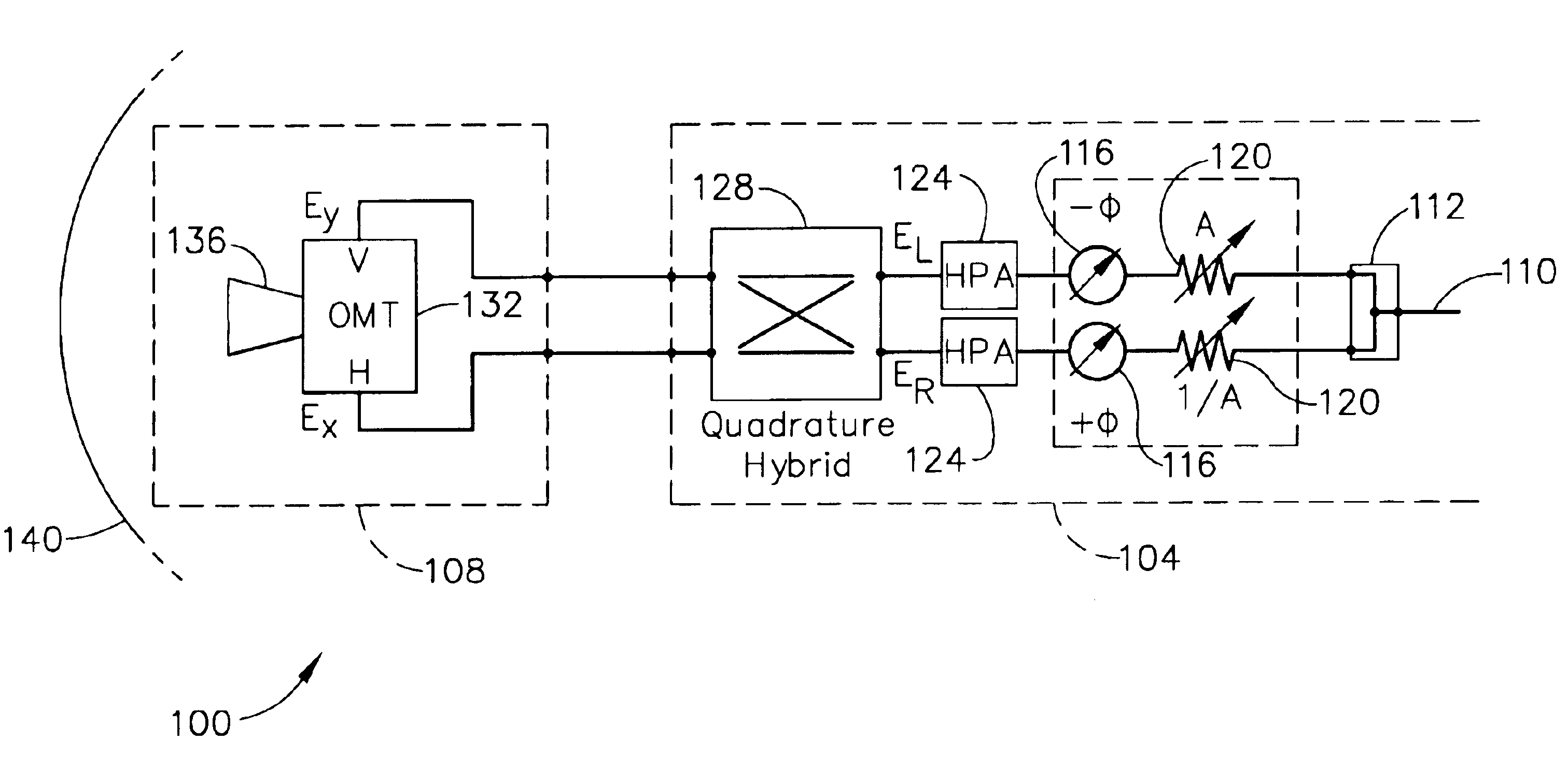
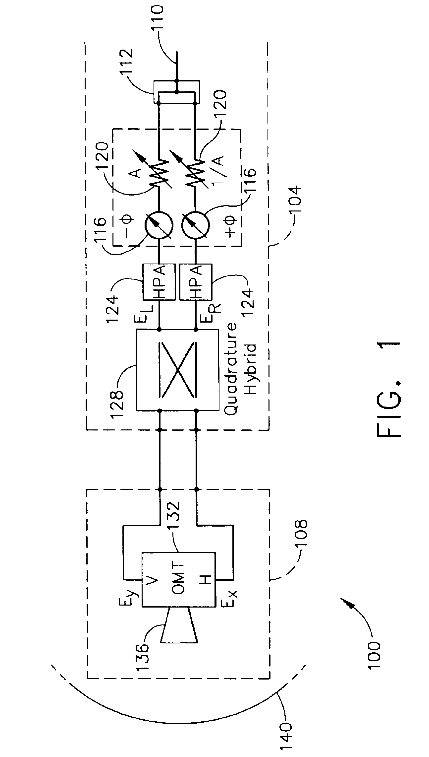
[0022]A polarization control apparatus that provides radome depolarization compensation according to one embodiment of the present invention is indicated generally in FIG. 1 by reference number 100. Although the apparatu...


PUM


Abstract

A method of reducing depolarization of a wireless signal passing through an antenna radome. An angle of incidence of the signal relative to the radome is determined. From the determined angle of incidence, at least one offset to signal depolarization attributable to the radome is determined. The offset is applied to the signal to reduce depolarization of the signal. When the foregoing method is implemented, effects of radome depolarization in transmit and / or receive modes can be substantially reduced or eliminated.

Description

FIELD OF THE INVENTION[0001]The present invention relates generally to antenna systems and, more particularly, to a system and method for compensating for depolarization of a signal passing through a radome of an antenna system.BACKGROUND OF THE INVENTION[0002]An antenna system in an aircraft or other vehicle is typically covered by an aerodynamically shaped radome. The antenna system illuminates the radome surface at oblique angles of incidence over at least part of the antenna scan range. Radomes, however, tend to cause depolarization of electromagnetic waves passing through them at oblique incidence. Thus a cross-polarization level of a signal may increase as the signal passes through a radome at an oblique angle.[0003]Radome wall design can be modified, for example, by adjusting thicknesses of the core and central skin to reduce depolarization. Studies have shown, however, that such improvements have only limited effect and may increase transmission loss, radome weight and costs...

Claims


Application Information

Patent Timeline
Patent Type & Authority Patents(United States)
IPC IPC(8): H01Q21/24H01Q1/28H01Q1/27H01Q1/42H04B1/18
CPCH01Q1/281H01Q1/42H01Q21/245
Inventor MONK, ANTHONY D.
Owner THE BOEING CO
Why Eureka
Try Eureka