Stereoscopic panoramic image capture device

Inactive Publication Date: 2005-09-20
DD MICOY INC
View PDF27 Cites 145 Cited by
  • Summary
  • Abstract
  • Description
  • Claims
  • Application Information

AI Technical Summary

Benefits of technology

[0007]In an advantage provided by this invention, an image ca

Problems solved by technology

Although such devices are suitable for stationary images, such devices typically produce blurred or distorted images when used to capture non-stationary objects.
Although such systems substantially eliminate the problem associated with capturing objects in motion, such systems do not provide means for producing a stereoscopic image.
S

Method used


Image

  • Stereoscopic panoramic image capture device
  • Stereoscopic panoramic image capture device
  • Stereoscopic panoramic image capture device

Examples


Embodiment Construction

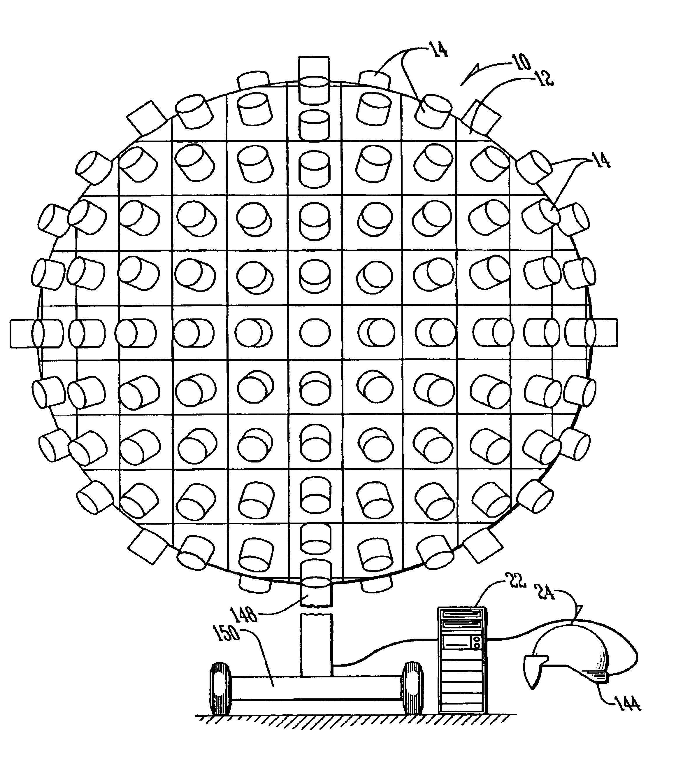
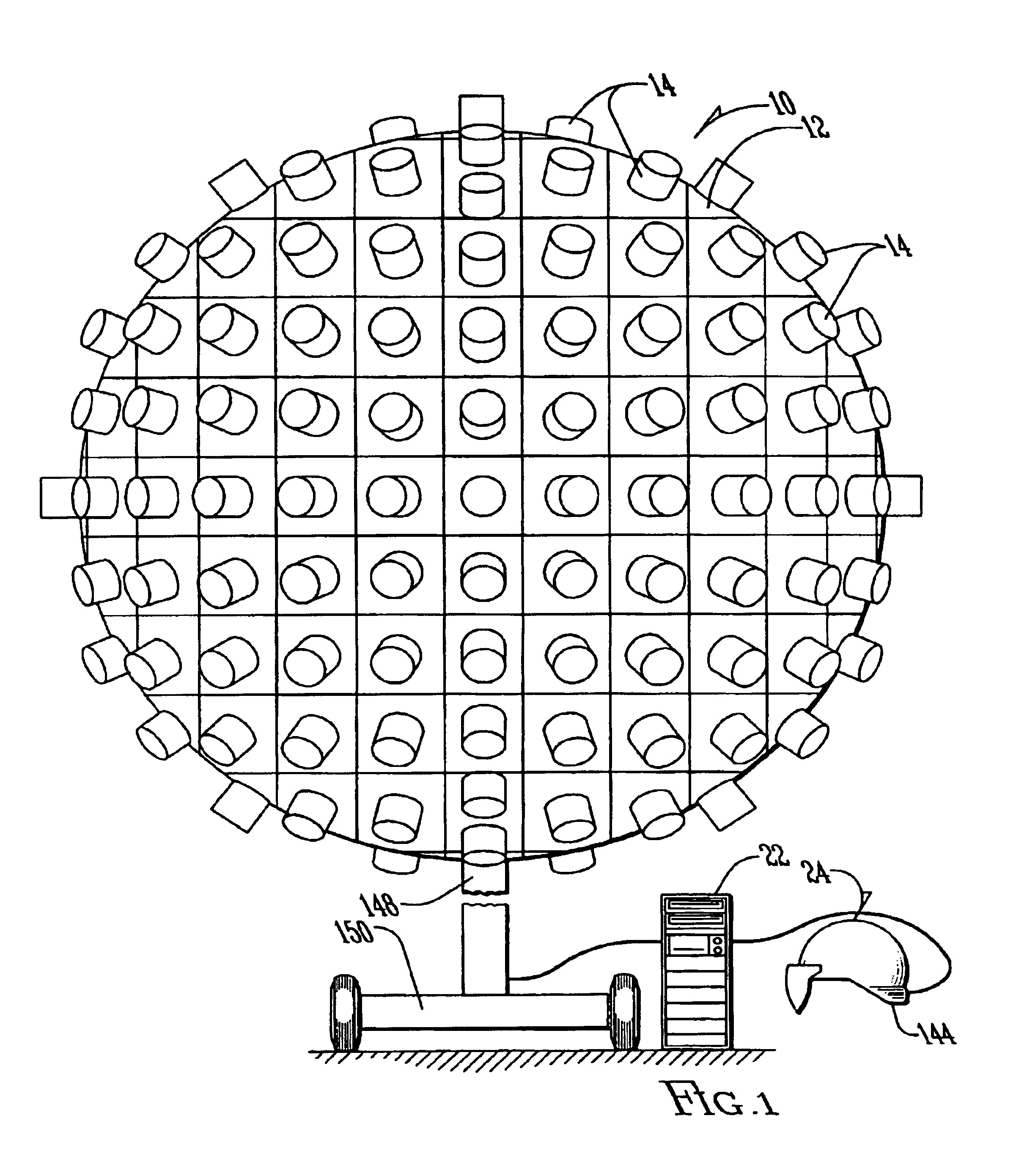
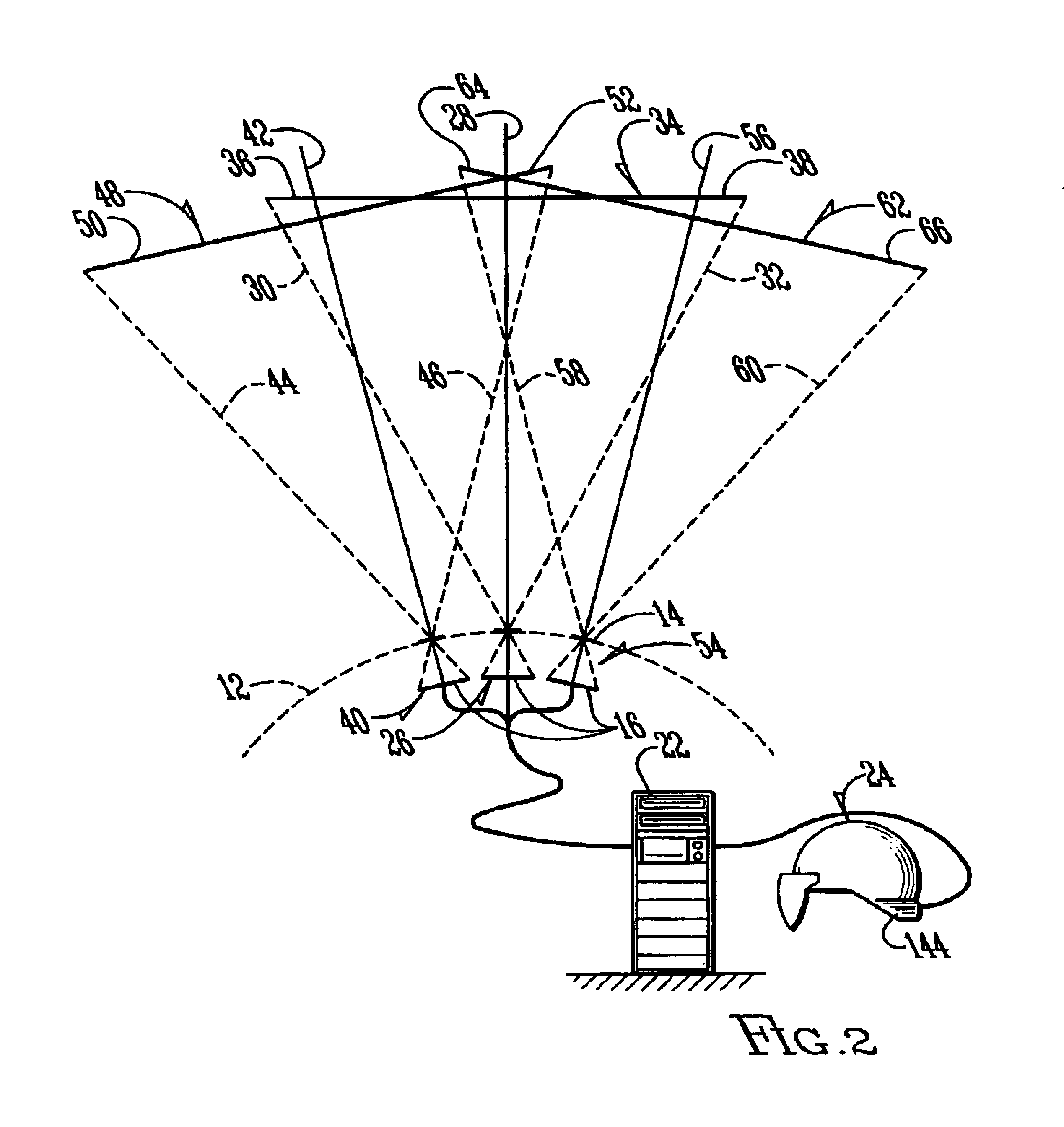
[0022]Referring to FIG. 1, a camera (10) is shown having a body (12) constructed of plastic or other similar lightweight material. In the preferred embodiment, the body (12) is substantially spherical, having a diameter preferably between 0.001 and 500 centimeters, and more preferably, between 10 and 50 centimeters. Provided substantially equally spaced across the surface of the body (12) are a plurality of lenses (14). The lenses (14) are preferably circular lenses having a diameter of preferably between 5 angstroms and 10 centimeters, and more preferably, between 0.5 and 5 centimeters. In the preferred embodiment, the lenses are model number BCL38C 3.8 millimeter micro lenses, manufactured by CBC America, located at 55 Mall Drive, Commack, N.Y. 11725. As shown in FIG. 2, the lenses (14) are each associated with a charge coupled device (CCD) assembly (16), such as those well known in the art. Although in the preferred embodiment a GP-CX171 / LM CCD color board camera, manufactured by...


PUM


Abstract

An imaging system comprising a plurality of first image capture devices. Overlapping rectilinear images are captured and halved, with the left halves being stitched and transformed into a first equirectangular image and the right halves being stitched and transformed into a second equirectangular image. The first equirectangular image, and second equirectangular image are displayed in a stereoscopic orientation to produce a stereoscopic equirectangular image. The imaging system may be utilized to capture a plurality of sequential images, to produce a full-motion stereoscopic equirectangular image.

Description

BACKGROUND OF THE INVENTION[0001]1. Field of the Invention[0002]The present invention relates in general to a panoramic image capture device and, more specifically, to a panoramic image capture device for producing a stereoscopic panoramic image.[0003]2. Description of the Prior Art[0004]Panoramic cameras are known in the art. Such cameras often use a single, rotatable camera. Although such devices are suitable for stationary images, such devices typically produce blurred or distorted images when used to capture non-stationary objects. It is also known in the art to utilize an image capture system having a plurality of image capture devices. In this manner, a plurality of images can be captured, substantially simultaneously, and stitched together using processes known in the art. Although such systems substantially eliminate the problem associated with capturing objects in motion, such systems do not provide means for producing a stereoscopic image.[0005]It is also known in the art ...

Claims


Application Information

Patent Timeline
IPC IPC(8): H04N13/00H04N5/262H04N13/02H04N15/00
CPCH04N5/23238H04N5/2628H04N13/0242G06T7/0024H04N13/0059H04N13/0221H04N13/0239H04N13/0285H04N13/0434H04N13/044H04N2013/0081H04N2013/0088G06T7/30H04N13/337H04N13/243H04N13/344H04N13/194H04N13/221H04N13/286H04N13/239H04N23/698
Inventor PIERCE, DONALDHERRNSTADT, STEVEN M.GROVER, TRENTGOOD, FREDERICK
Owner DD MICOY INC
Why Eureka
Try Eureka