Apparatus and method for optical raster-scanning in a micromechanical system
Inactive Publication Date: 2005-09-20
RGT UNIV OF CALIFORNIA
View PDF8 Cites 29 Cited by
Summary
Abstract
Description
Claims
Application Information
AI Technical Summary
This helps you quickly interpret patents by identifying the three key elements:
Problems solved by technology
Method used
Benefits of technology
[0011]The invention provides an improved optical raster-scanning micromechanical system. Mirror performance in the system is improved through the technique of characterizing a
Problems solved by technology
In a two mirror system including a fast mirror and a slow mirror, fast mirror wobble of less than 1% of the total deflection angle will cause scan lines to overlap and seriously degrade image quality.
In the slow mirror, rotational errors known a
Method used
Image
Click on the blue label to locate the original text in one second.
Reading with bidirectional positioning of images and text.
Examples
Embodiment Construction
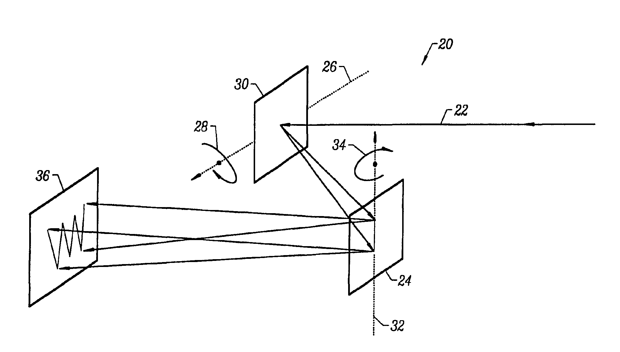
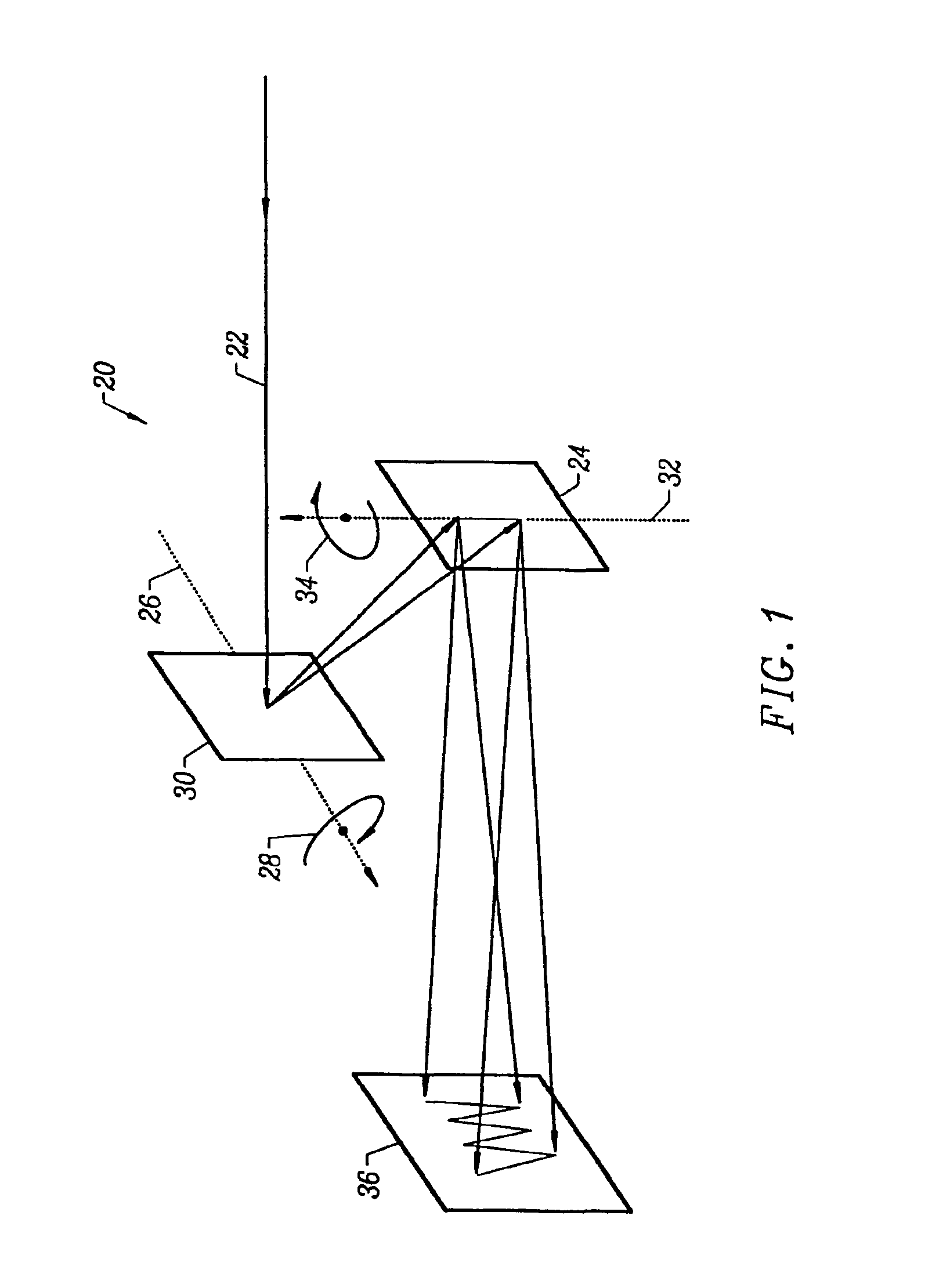
[0027]FIG. 1 is a simplified representation of an optical raster scanning system 20 constructed in accordance with an embodiment of the invention. The system 20 processes a laser beam 22 with a first mirror 30, implemented as a micromechanical device. The first mirror 30 may be a “fast mirror”, as described below, which pivots about a first axis of rotation 26, causing first rotational motion, as shown with arrow 28. As described below, the first rotational motion is achieved by pushing or pulling the bottom edge of the mirror 30.
[0028]FIG. 1 also illustrates a second mirror 24, which is also implemented as a micromechanical device. The second mirror 24 may be a “slow mirror”, as described below, which pivots about a second axis of rotation 32, causing second rotational motion, as shown with arrow 34. As described below, the second rotational motion is achieved by pushing or pulling the left and right sides of the mirror 24. By controlling the motion of the slow mirror 24 and the fa...
PUM
Abstract
A method of operating a micromechanical scanning apparatus includes the steps of identifying a radius of curvature value for a micromechanical mirror and modifying a laser beam to compensate for the radius of curvature value. The identifying step includes the steps of measuring the far-field optical beam radius of a laser beam reflected from the micromechanical mirror. The measured far-field optical beam radius is then divided by a theoretical far-field optical beam radius reflected from an ideal mirror to yield a ratio value M. An analytical expression for M is curve-fitted to experimental data for M with the focal-length as a fitting parameter. The focal-length value determined by this procedure, resulting in a good fit between the analytical curve and the experimental data, is equal to half the radius of curvature of the micromechanical mirror. The micromechanical scanning apparatus is operated by controlling the oscillatory motion of a first micromechanical mirror with a first micromechanical spring and regulating the oscillatory motion of a second micromechanical mirror with a second micromechanical spring.
Description
[0001]This application is a DIV of application Ser. No. 10 / 052,148 filed Jan. 16, 2002, U.S. Pat. No. 6,603,588, which is a DIV of application Ser. No. 09 / 714,053 filed Nov. 15, 2000, U.S. Pat. No. 6,347,002, which is a DIV of application Ser. No. 09 / 337,016 filed Jun. 30, 1999, U.S. Pat. No. 6,246,504.[0002]The development of the technology described herein was supported by NSF Grant No. EEC-96-15774 for the study of high-speed, high-resolution micro-optical scanners. The U.S. Government may have certain rights in this technology.BRIEF DESCRIPTION OF THE INVENTION[0003]This invention relates generally to optical scanners and displays. More particularly, this invention relates to an optical raster-scanning microelectromechanical system.BACKGROUND OF THE INVENTION[0004]Scanning micromirrors fabricated using surface-micromachining technology are known in the art. As used herein, a micromirror, a microscopic device, a micromachined device, a micromechanical device, or a microelectromec...
Claims
Application Information
Patent Timeline
Application Date:The date an application was filed.
Publication Date:The date a patent or application was officially published.
First Publication Date:The earliest publication date of a patent with the same application number.
Issue Date:Publication date of the patent grant document.
PCT Entry Date:The Entry date of PCT National Phase.
Estimated Expiry Date:The statutory expiry date of a patent right according to the Patent Law, and it is the longest term of protection that the patent right can achieve without the termination of the patent right due to other reasons(Term extension factor has been taken into account ).
Invalid Date:Actual expiry date is based on effective date or publication date of legal transaction data of invalid patent.