Surgical microscope

a surgical microscope and microscope technology, applied in the field of surgical microscopes, can solve the problems of system imbalance, system no longer in equilibrium and must be balanced, and increase the overall weight without optimal balance, so as to minimize the stress on individual guidance elements

Inactive Publication Date: 2005-09-20
LEICA INSTR SINGAPORE PTE
View PDF15 Cites 10 Cited by
  • Summary
  • Abstract
  • Description
  • Claims
  • Application Information

AI Technical Summary

Benefits of technology

[0007]It is the object of the invention to create an apparatus that allows the surgical microscope to be balanced out easily and quickly and that avoids the disadvantages of the known approaches, in particular the installation of additional weights or single-side attachments.
[0009]The actual guidance system of the optics carrier is thus located outside the virtual pivot axis. Since the center of gravity of the optics carrier is often located in the vicinity of the optical system, it is thus possible to place the virtual pivot axis exactly in the center of gravity of the optics carrier without thereby adversely affecting the optical system with real shafts or the like. This allows additional devices to be connected to the microscope even in the vicinity of the axis—and moreover on both sides of the microscope—with no need to install an additional counterweight (additional weight) on the optics carrier. The overall weight of the optics carrier is thus reduced as compared to the known configuration of the applicant's optics carrier (WO 97 13997 A1). A consequence of this is a reduction in the overall inertia and weight of the entire assemblage. This results in smooth adjustability.
[0013]Displacement of the arc-segment-shaped guidance element is advantageously accomplished by way of linear slides. These slides enable accurate guidance and are capable of absorbing forces and also any tilting moments that may occur.
[0014]If the accessory on the microscope is changed, the overall center of gravity of the optics carrier very often shifts at least two-dimensionally. Two slides arranged substantially perpendicular to one another are therefore advantageously provided in order to balance out the system. Displacement of the arc-segment-shaped guidance element and thus also of the virtual axis is therefore possible. The virtual axis can thus easily be placed in the center of gravity of the optics carrier.
[0015]For rapid and precise balancing of the optics carrier, displacement of the arc-segment-shaped guidance element is advantageously accomplished by means of threaded spindles. These threaded spindles are preferably self-locking. Additional clamping is therefore usually not necessary.
[0022]Two guidance elements arranged parallel to one another are preferably provided. This minimizes the stress on the individual guidance elements due to forces and moments that occur.

Problems solved by technology

If they are not equalized, brakes or bracing devices must then be present; these in turn disadvantageously increase the overall weight without optimally balancing (hysteresis).
In many cases, however, these accessories result in a displacement of the overall center of gravity.
As a result, the system is no longer in equilibrium and must be balanced out again.
This method is very time-consuming, however, and also creates elevated forces and moments at the stand.
Disadvantageously, the left-side attachment eliminates the possibility of mounting accessories there as well.

Method used


Image

  • Surgical microscope
  • Surgical microscope
  • Surgical microscope

Examples


Embodiment Construction

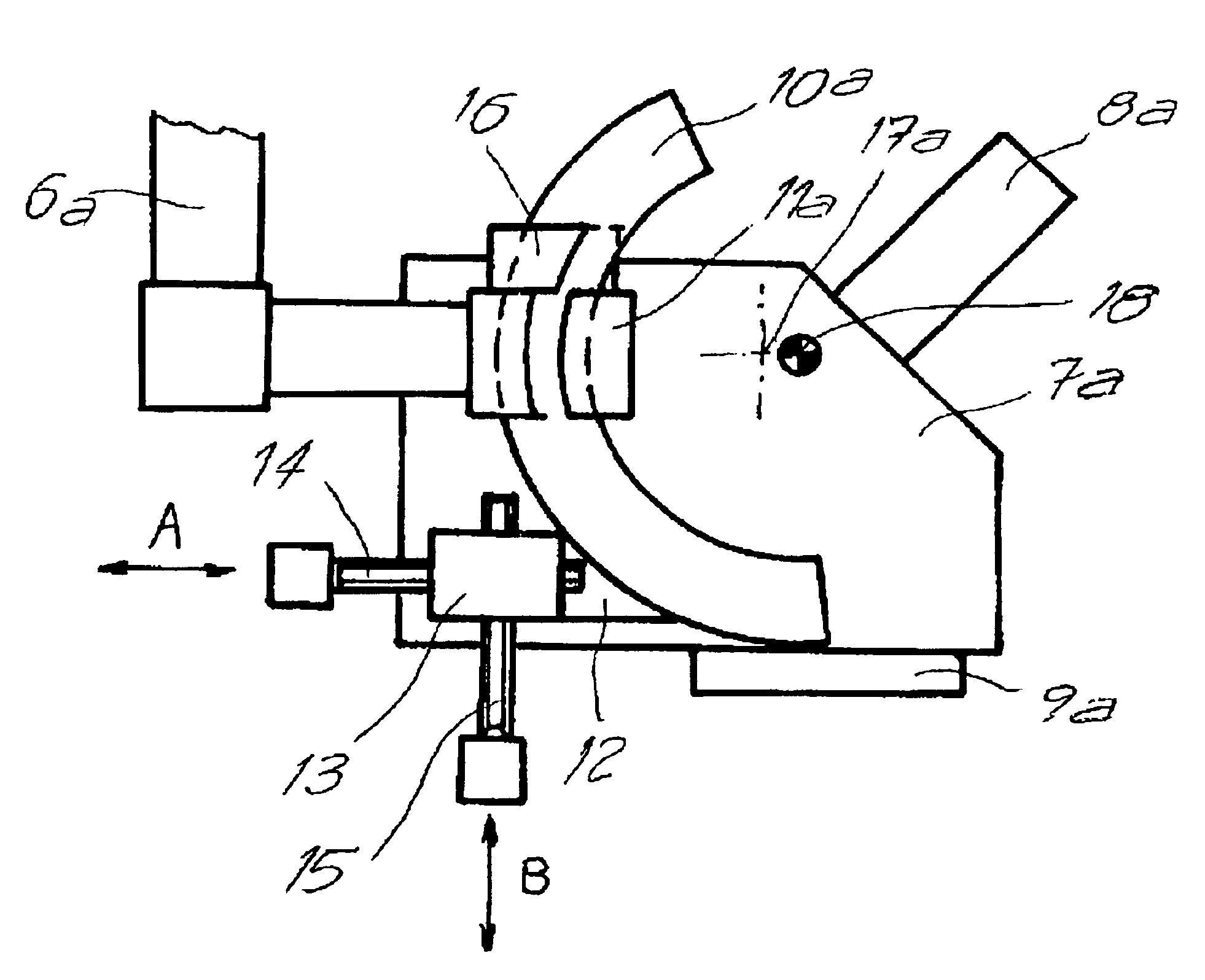
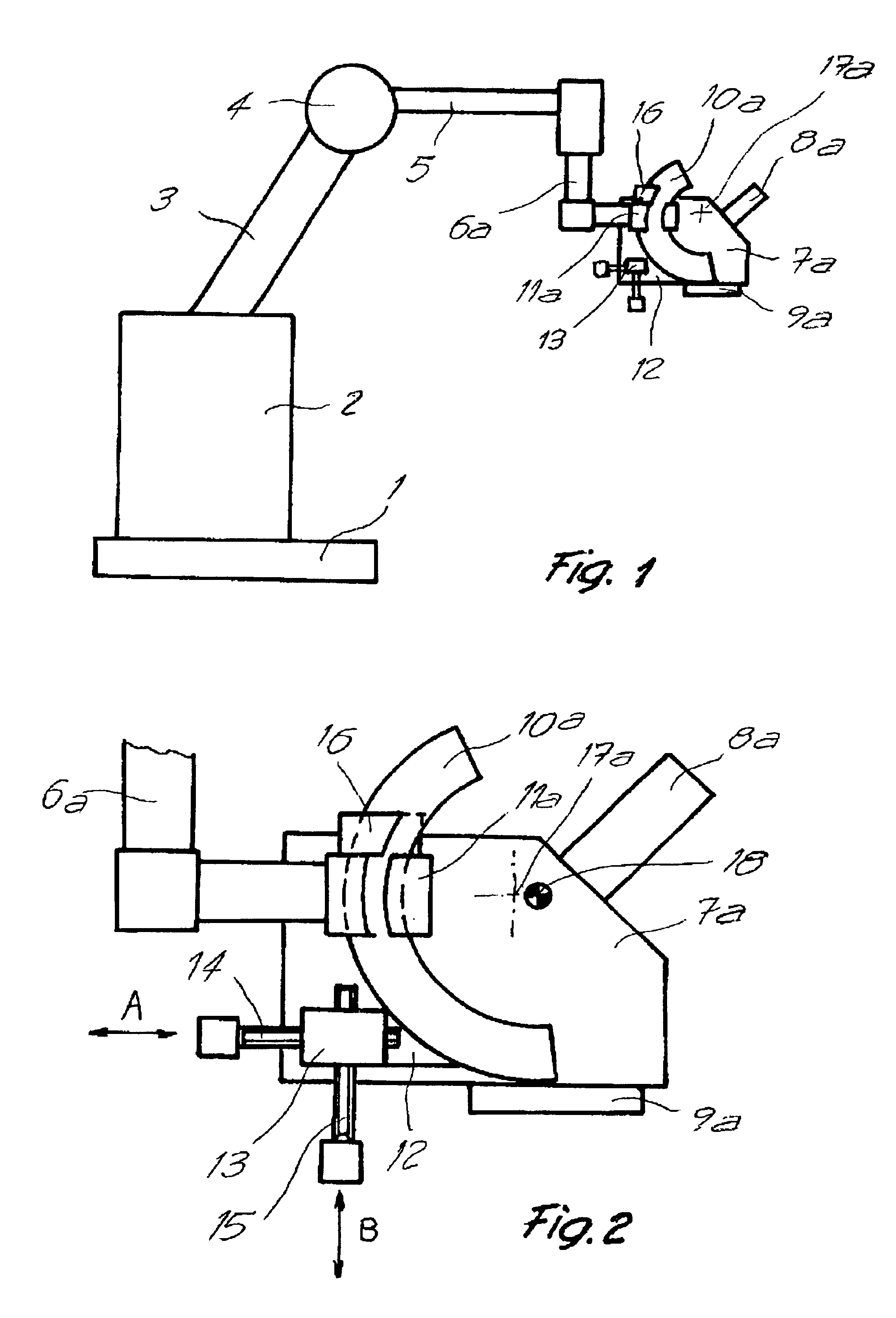
[0027]The surgical microscope visible in FIG. 1 comprises a stand that is substantially made up of a stand foot 1, a stand column 2, and an extension arm 3 mounted in stand column 2. A carrier arm 5 is connected via a joint 4 to extension arm 3. Suspended at the free end of carrier arm 5 is a pivot support 6a that is movable in a horizontal plane. An optics carrier 7a is joined, movably in multiple axes, to pivot support 6a. A tube 8a and an objective 9a are depicted on optics carrier 7a as examples of exchangeable accessories.

[0028]The term “stand” for purposes of the invention is to be understood to mean all retaining systems that retain a pivot support movably with respect to its surroundings; this applies, for example, to wall, floor, and ceiling mounts. The configuration of the stand is not significant for the invention.

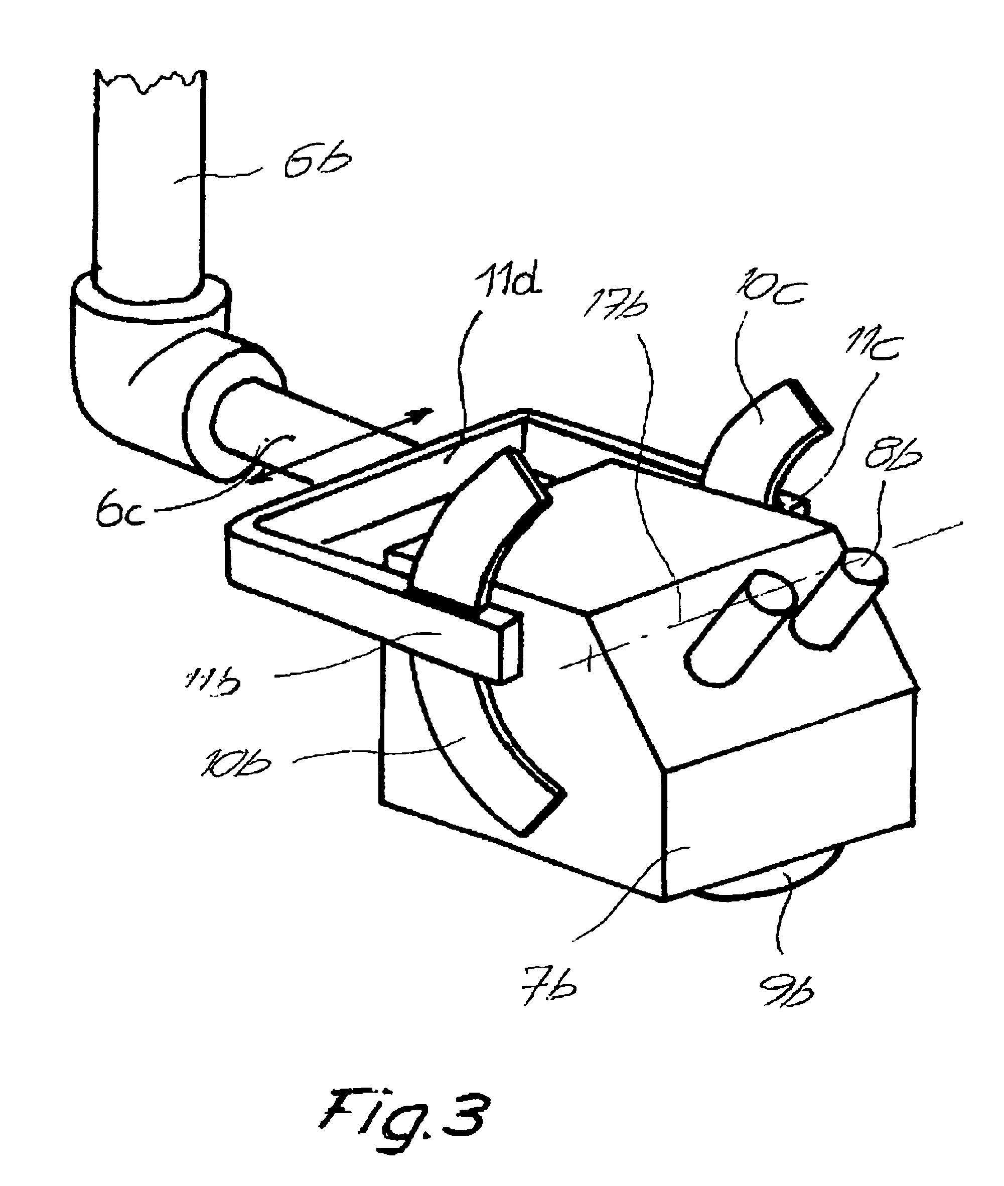
[0029]Optics carrier 7a is joined to pivot support 6a by way of an arc-segment-shaped guidance element 10a and a guide carriage 11a coacting therewith. In this ...


PUM


Abstract

The invention concerns a surgical microscope having a stand and having an optics carrier (7a) joined movably to the stand and mounted movably with respect to the stand. The optics carrier (7a) is mounted, in the region of its center of gravity, pivotably about at least one axis (17a) with respect to a pivot support (6a) of the stand. At least one of the pivot axes (17a) is constituted virtually by the center of an arc-segment-shaped guidance element (10a) that coacts with a guide carriage (11a).

Description

CROSS REFERENCE TO RELATED APPLICATIONS[0001]This application claims priority of the German patent application 101 55 719.1 filed Nov. 13, 2001 which is incorporated by reference herein.FIELD OF THE INVENTION[0002]The invention concerns a surgical microscope having a stand and having an optics carrier joined movably to the stand and mounted movably with respect to the stand, the optics carrier being mounted, in the region of its center of gravity, pivotably about at least one axis with respect to a pivot support of the stand.BACKGROUND OF THE INVENTION[0003]Surgical microscopes must be very movable and must be quickly adjustable without great energy expenditure. To ensure that the microscope does not shift by itself once a position has been established, the forces and moments occurring in each location must be equalized. If they are not equalized, brakes or bracing devices must then be present; these in turn disadvantageously increase the overall weight without optimally balancing (...

Claims


Application Information

Patent Timeline
Patent Type & Authority Patents(United States)
IPC IPC(8): A61B19/00F16M11/12F16M11/02F16M11/10G02B7/00A61B90/50G02B21/24
CPCA61B19/26F16M11/10F16M11/12F16M11/2064G02B7/001A61B19/5223A61B90/50A61B90/20A61B90/25
Inventor METELSKI, ANDRZEJ
Owner LEICA INSTR SINGAPORE PTE
Why Eureka
Try Eureka